Load carrying capacity and life
Basic load ratings
Basic load ratings are key data specific to the plain bearings that are not standardised and may differ from manufacturer to manufacturer. They are derived from the material-specific load parameters K and the projected load-bearing area of the bearing in each case.
Basic dynamic load rating
The basic dynamic load rating Cr or Ca is used in cases of dynamic loading. A plain bearing is subjected to dynamic loading if it performs rotary, swivel, tilt or linear motion under load.
The basic dynamic load rating is the maximum permissible dynamic load. In the case of radial spherical plain bearings, it can be utilised to the full only if the load acts purely in a radial direction. In the case of axial spherical plain bearings, it can be utilised to the full only if the load acts purely in a concentric, axial direction.
If the basic dynamic load rating is utilised to the full, there is often a considerable reduction in the operating life of the bearings. The degree to which the basic load rating is utilised should therefore always be matched to the required operating life. The basic load rating depends on the sliding contact surface and influences the rating life of the plain bearings.
Basic static load rating
The basic static load rating C0r or C0a is used if a plain bearing is subjected to load while stationary.
It indicates the load that the plain bearing can support at room temperature without damage to the bearing. This is subject to the precondition that the components adjacent to the bearing must prevent deformation of the bearing.
ACHTUNG
If the basic load rating C0r or C0a is utilised to the full, the shaft and housing must be made from high strength materials.
Bearing load
The bearing load describes the external forces acting on the bearing.
Concentric constant force F
For calculation of the static load safety factor, the specific load and the rating life, load values can be taken directly into consideration under the following preconditions:
- Loads act in a radial direction only on radial spherical plain bearings, angular contact spherical plain bearings and cylindrical plain bushes.
- Loads act in an axial direction only on axial spherical plain bearings.
- Loads do not vary in their magnitude and direction during operation.
Concentric constant radial force F
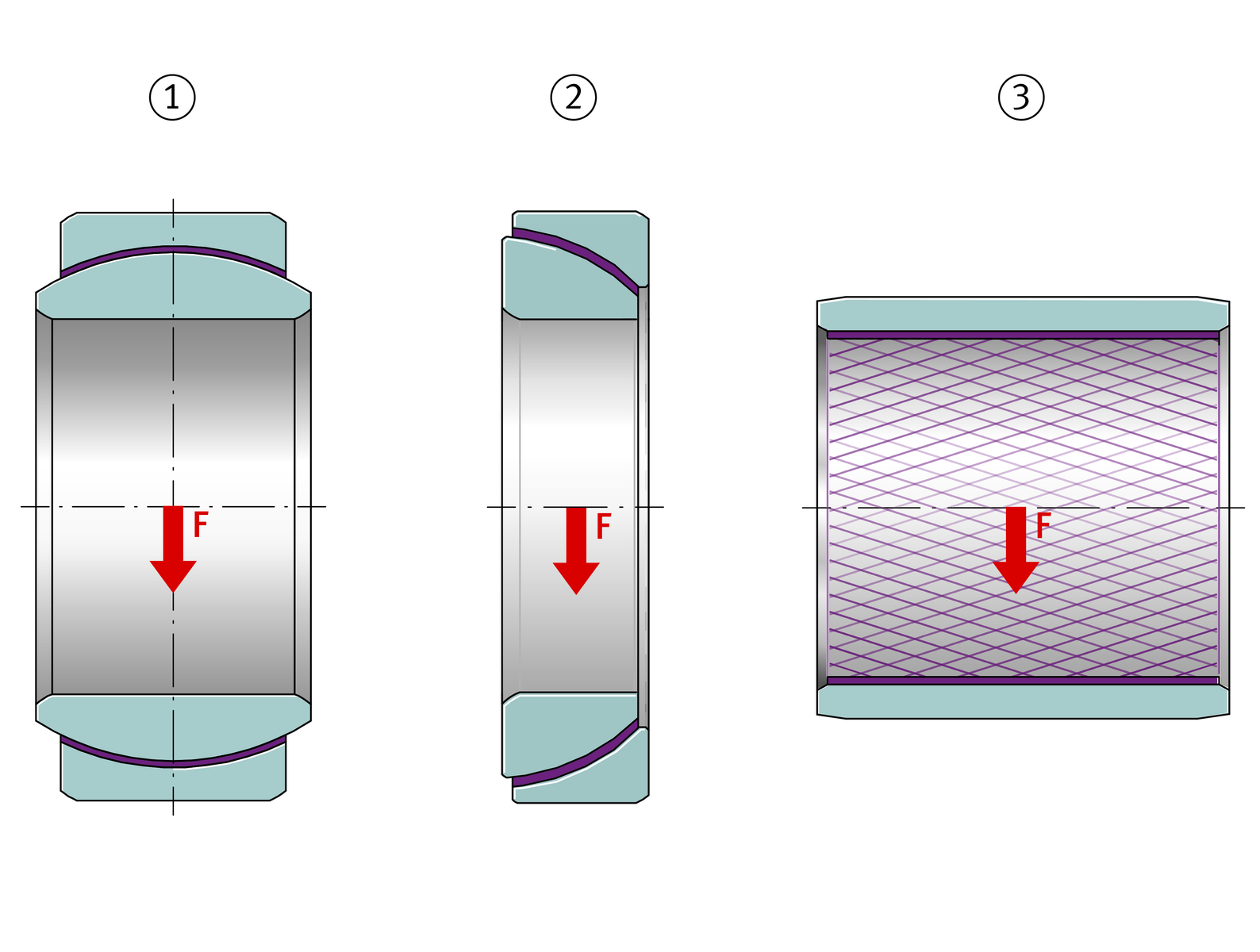


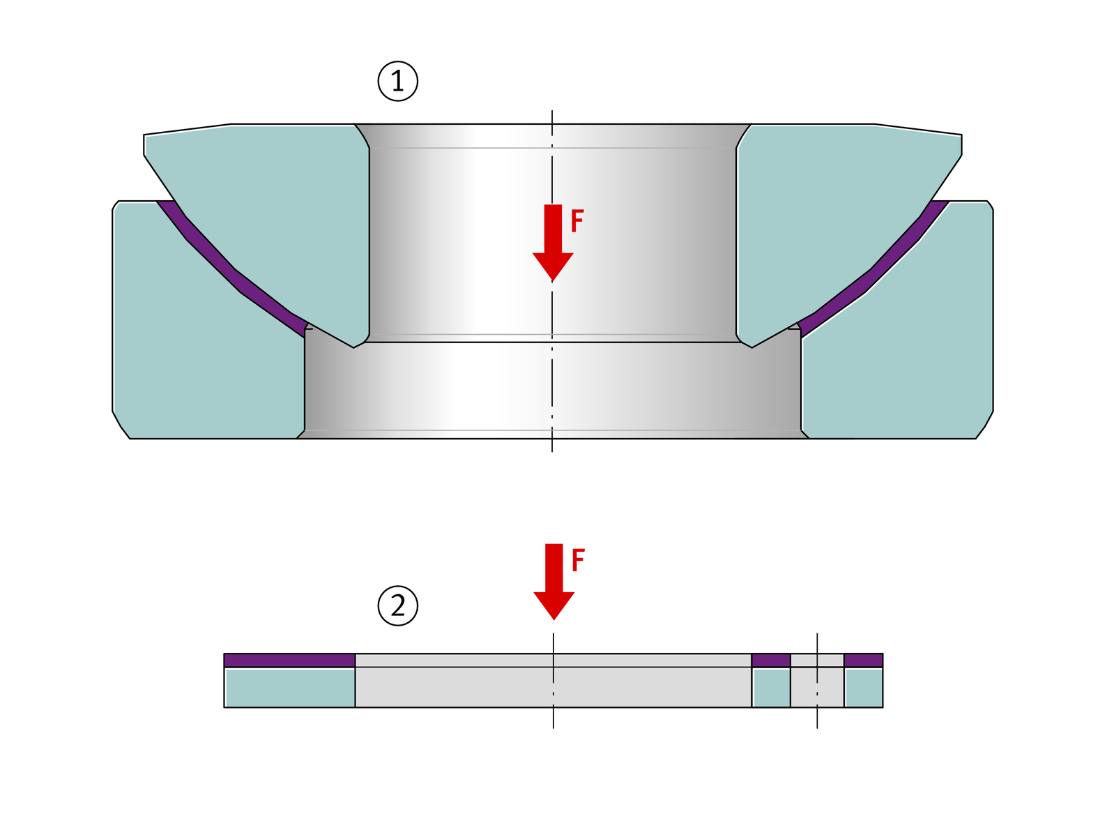
Concentric constant axial force F
Concentric variable force F
If the concentric force varies in magnitude during motion, rating life calculation and checking of the permissible specific load must be carried out on the basis of the maximum force Fmax.
One possible influence on the rating life as a result of pulsating or alternating loads is taken into consideration by means of the correction factor fHz, see link.
Variable bearing load
Combined loading by radial and axial forces
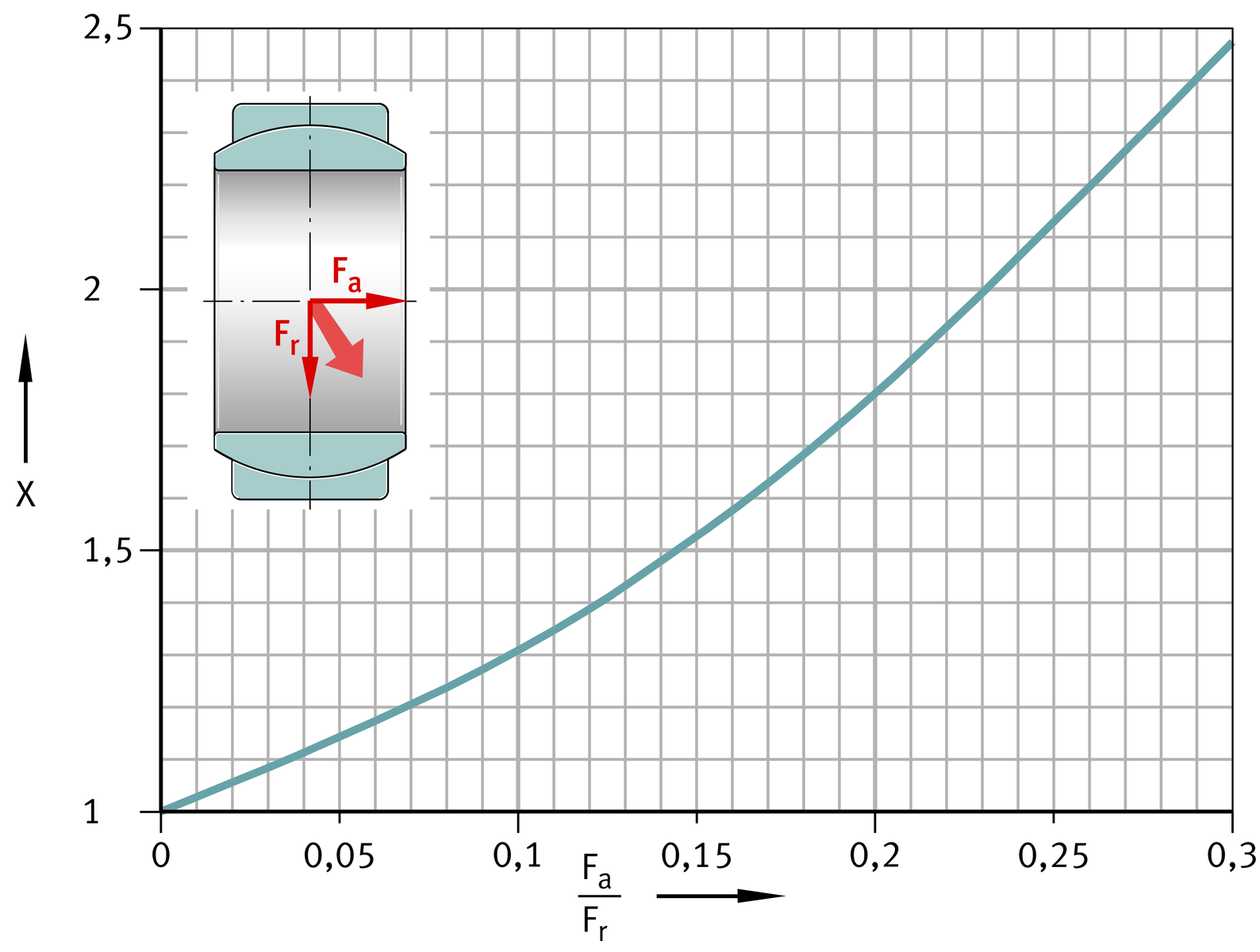
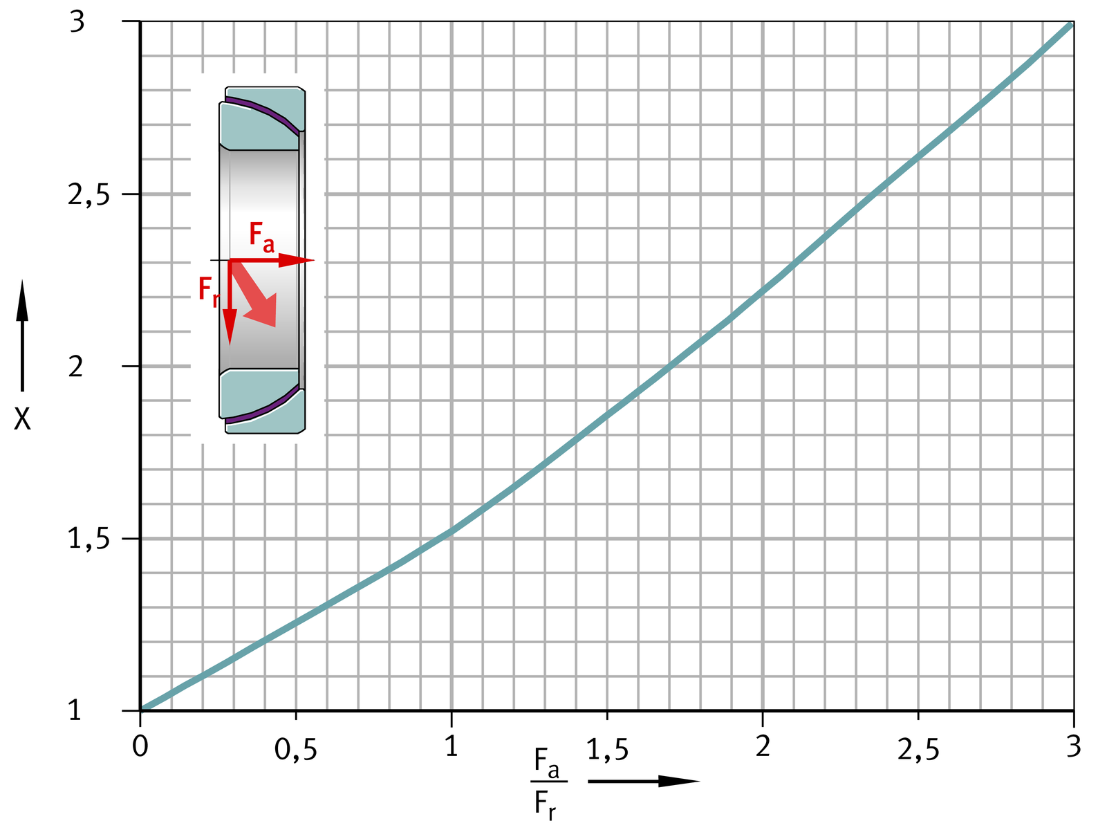
If spherical plain bearings are subjected simultaneously to radial and axial loads, combined loading is present. The equivalent static bearing load is calculated on a similar basis to the equivalent dynamic bearing load. The permissible ranges for the ratio Fa/Fr are valid for static and for dynamic loading.
In the case of dynamic loading, the equivalent dynamic bearing load P must be used in rating life calculation. This values takes the combined forces into consideration in rating life calculation.
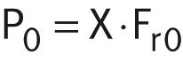
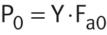
In the case of static loading, the equivalent static bearing load P0 must be used in calculation of the static load safety factor. This value takes the combined forces into consideration in calculation of the static load safety factor.
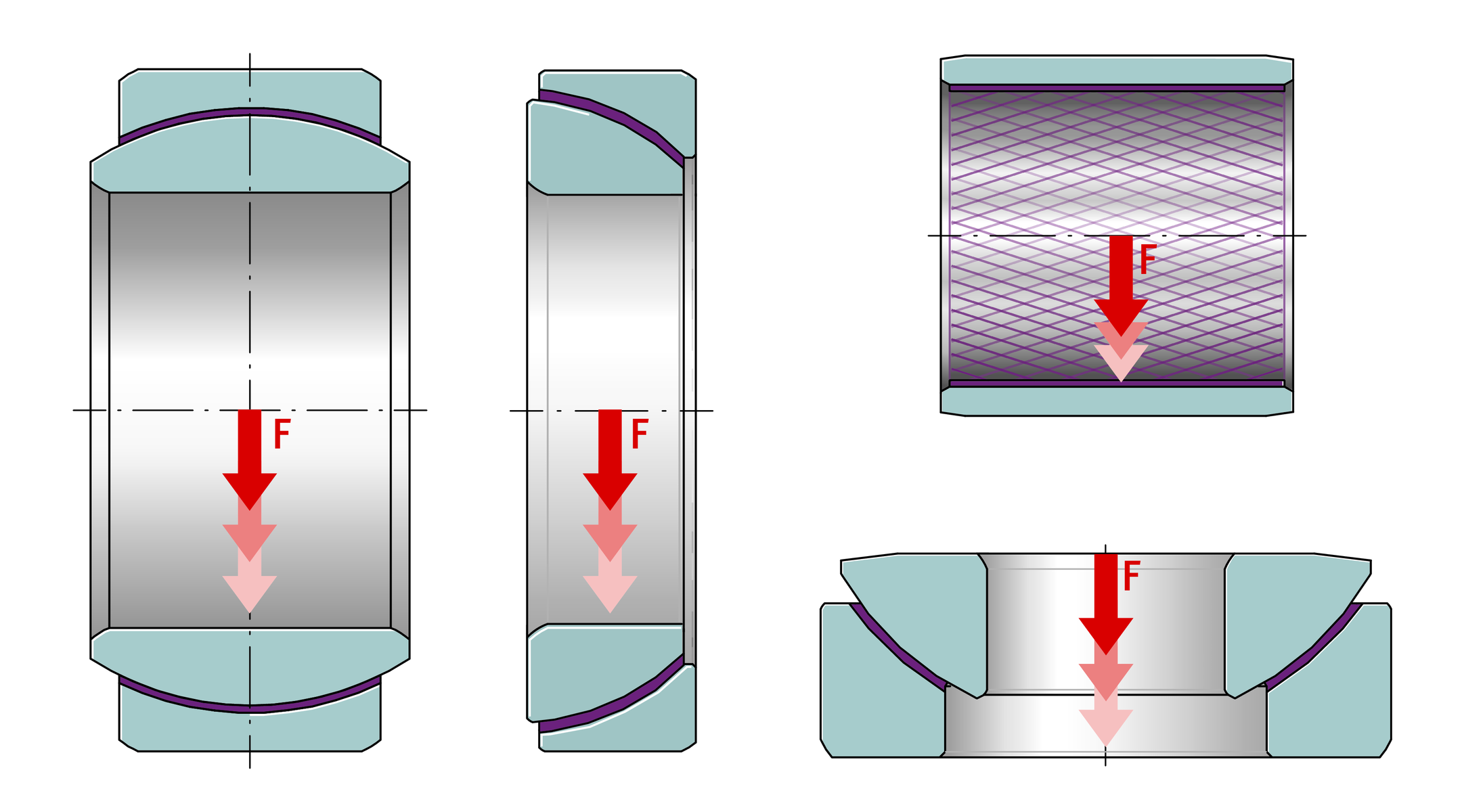
Calculation of radial and angular contact spherical plain bearings, ➤ Figure and ➤ Figure :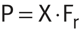
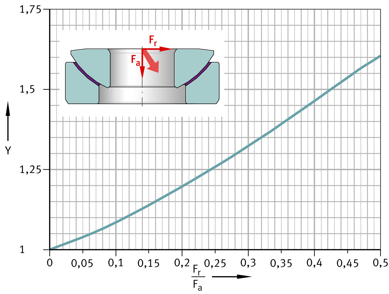
 Calculation of axial spherical plain bearings, ➤ Figure :
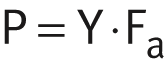
| P | N | Equivalent dynamic bearing load |
| X | Axial load factor for radial and angular contact spherical plain bearings, ➤ Figure and ➤ Figure | |
| Fr | N | Radial dynamic bearing load |
| P0 | N | Equivalent static bearing load |
| Fr0 | N | Radial static bearing load |
| Y | Radial load factor for axial spherical plain bearings, ➤ Figure | |
| Fa | N | Axial dynamic bearing load |
| Fa0 | N | Axial static bearing load. |
ACHTUNG
The correct spherical plain bearing is selected as follows:
- The permissible range for the ratio Fa/Fr in the case of radial spherical plain bearings is between 0 and 0,3.
- If the ratio Fa/Fr exceeds the value 0,3, angular contact spherical plain bearings can be used. Their ratio Fa/Fr extends to a value of 3, since they can support higher axial forces.
- If the axial forces are more than twice the radial forces, axial spherical plain bearings can be used.
Radial spherical plain bearings,
combined loading
Angular contact spherical plain bearings,
combined loading
Axial spherical plain bearings,
combined loading
Static load safety factor
Before the rating life is calculated, it is advisable to check the static load safety factor.
The static load safety factor S0 is the ratio between the basic static load rating C0 and the equivalent static load P0: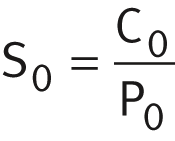
| S0 | Static load safety factor | |
| C0 | N | Basic static load rating |
| P0 | N | Equivalent static bearing load. |
ACHTUNG
The static load safety factor must always be >1. Any instructions relating to specific series must be observed.
Specific bearing load
The specific bearing load describes the contact pressure present in the bearing in the dynamic state. It is the decisive criterion for assessing the suitability of a plain bearing in the particular application.
The specific bearing load occurring in a bearing is dependent on the load, the sliding contact surface, the lubrication conditions and the mounting situation. Due to the influence of these factors, precise calculation is not possible.
If the required operating life is to be achieved, the specific bearing load must be matched to the actual operating conditions.
ACHTUNG
Under extreme loading conditions, such as high axial load in the case of radial spherical plain bearings, elastic deformation of the bearing and housing may lead to contact pressure concentrations. Please contact Schaeffler in this case.
Calculation
The specific bearing load p for a plain bearing is calculated with the aid of the specific load parameter K.
Radial and angular contact spherical plain bearings: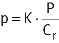 Axial spherical plain bearings:
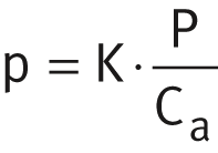 Bushes and radial component of flanged bushes:
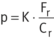 Thrust washers and axial component of flanged bushes:
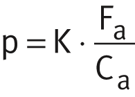
| p | N/mm2 | Specific bearing load |
| K | N/mm2 | Specific dynamic load parameter, see table |
| P | N | Equivalent dynamic bearing load, see link |
| Fr | N | Radial dynamic bearing load |
| Fa | N | Axial dynamic bearing load |
| Cr, Ca | N | Radial or axial basic dynamic load rating. |
ACHTUNG
For spherical plain bearings with ELGOGLIDE operated under the condition of the specific bearing load p ≦ 25 N/mm2, please consult Schaeffler.
Specific load parameter
Sliding layer, sliding contact surface | Specific dynamic load parameter K |
|---|---|
N/mm2 | |
ELGOGLIDE | 300 |
ELGOGLIDE-W11 | 300 |
PTFE composite | 100 |
PTFE film | 100 |
ELGOTEX | 140 |
E40, E40-B | 140 |
E50 | 70 |
Steel/steel | 100 |
Steel/bronze | 50 |
Alternative calculation method for bushes and thrust washers
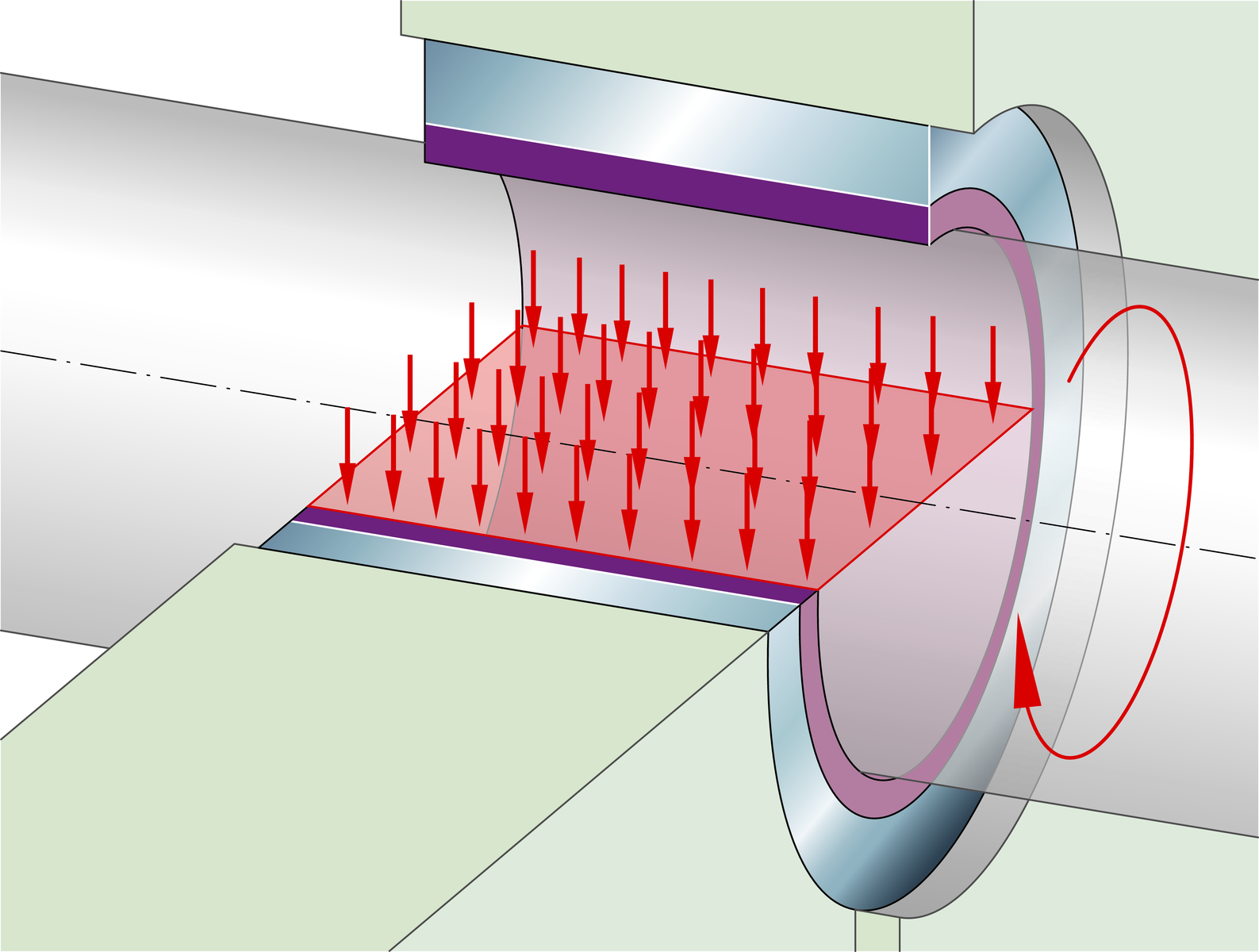
Due to the simple geometry of plain bushes EGB, ZWB and ZGB as well as flanged bushes EGF and thrust washers EGW, their specific bearing load can alternatively be determined by means of the following relationships. It is assumed in this case that there is uniform load distribution over the projected area, ➤ Figure.
Projected area of a bush
Alternative calculation
Bush: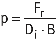 Flanged bush, radial force:
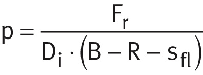 Flanged bush, axial force:
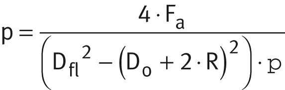 Thrust washer:
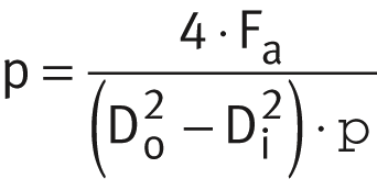
| p | N/mm2 | Specific bearing load |
| Fr | N | Radial dynamic bearing load |
| Di | mm | Inside diameter of bush, flanged bush or thrust washer |
| B | mm | Width of bearing |
| R | mm | Radius of flange |
| sfl | mm | Thickness of flange |
| Fa | N | Axial dynamic bearing load |
| Dfl | mm | Outside diameter of flange |
| Do | mm | Outside diameter of bush or thrust washer. |
Bearing motion
The bearing motion describes the dynamic conditions in the bearing. These are essentially indicated by the swivel angle and tilt angle, the velocity of motion and the frequency of motion.
Sliding velocity
The sliding velocity is dependent on the plain bearing and its diameter.
Rotary motion: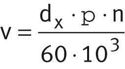 Swivel motion:
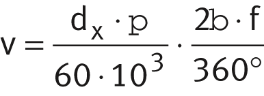
| v | m/s | Sliding velocity |
| dx | mm | Specific diameter, see table |
| n | min–1 | Operating speed |
| β | ° | Swivel angle, ➤ Figure |
| f | min–1 | Swivel frequency, ➤ Figure. |
ACHTUNG
For combined swivel and tilt motions in spherical plain bearings, the angle of motion β1 must be used, see link.
Specific diameter
Plain bearing | Specific diameter dx |
|---|---|
Radial spherical plain bearing | dK |
Axial spherical plain bearing | 0,7 · dK |
Angular contact spherical plain bearing | 0,9 · dK |
Bush | Di |
Flanged bush (radial sliding surface) | Di |
Flanged bush (axial sliding surface) | Dfl |
Thrust washer | Do |
Frequency of motion
The number of motions per time period, the frequency, has a significant influence on the operating life of spherical plain bearings.
In addition to the load, the coefficient of friction and the motion parameter, the frequency influences the frictional energy generated in the bearing. This is dependent on the relevant sliding contact surface and must not exceed the permissible pv values, see table.
ACHTUNG
The frequency can only be used for calculating the sliding velocity in applications with continuous operation or periodic stationary periods.
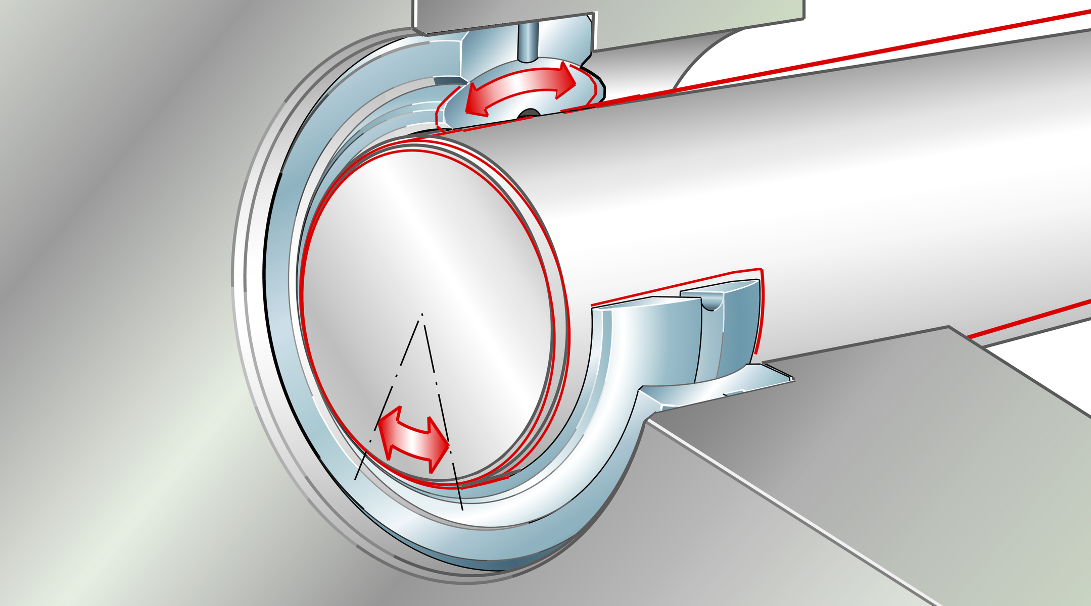
Swivel angle
Swivel motion is defined as relative motion with reversing direction about the bearing axis. In the case of spherical plain bearings, the two bearing rings move relative to each other, in the case of bushes the shaft and bush move relative to each other.
The centring angle described by the two return points is described as the swivel angle β, ➤ Figure. This describes the motion between the two extreme points.
Swivel motion and swivel frequency taking the example of a spherical plain bearing
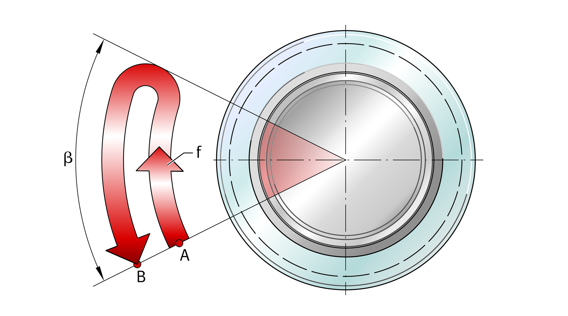
(number of motions from A to B per minute)
Tilt angle
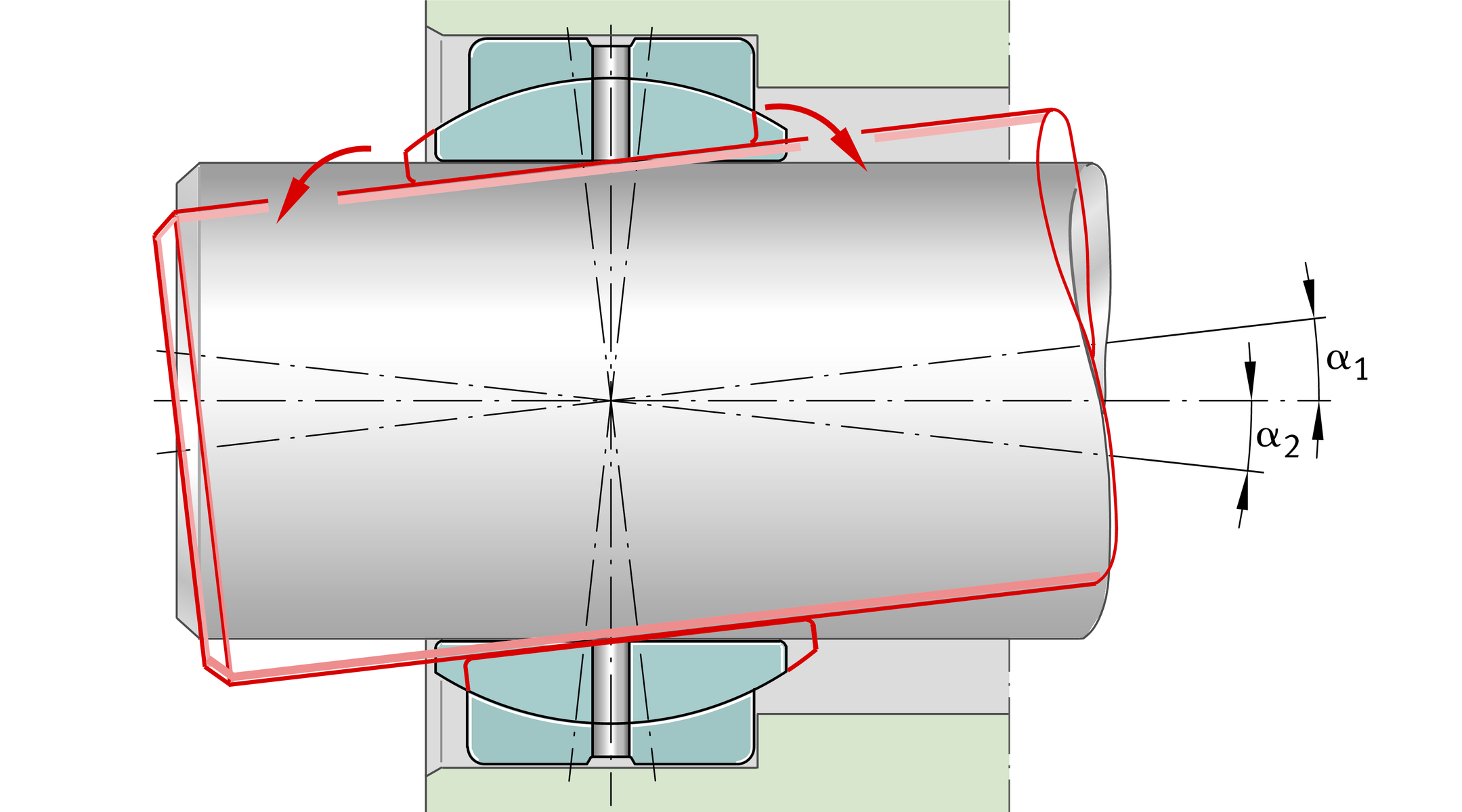
In tilt motion of spherical plain bearings, the inner ring and shaft locating washer move relative to the outer ring and housing locating washer in a direction transverse to the bearing axis. The axes of the relevant bearing rings intersect below the tilt angle α, ➤ Figure.
The maximum permissible tilt angle α must be observed. Full utilisation of the basic load ratings is only permissible within the stated tilt angle α.
Tilt motion
Combined swivel and tilt motion
The motion angle β1 corresponds to the resultant sliding distance in the case of simultaneous tilt and swivel motion, ➤ Figure.
Combined motions are calculated as follows: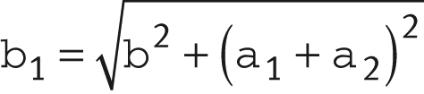
| β1 | ° | Motion angle corresponding to the sliding distance |
| β | ° | Swivel angle, see link |
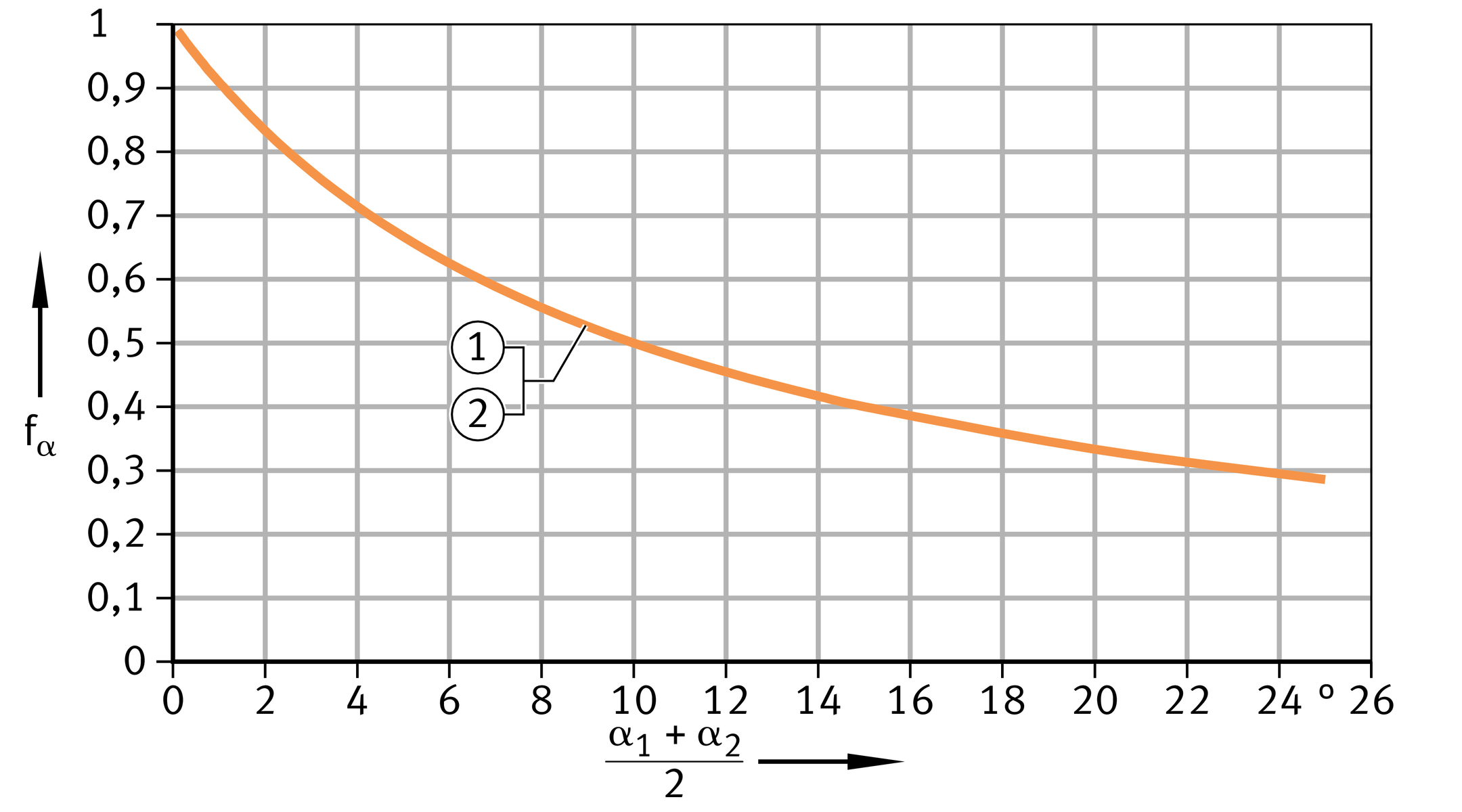
| α1 | ° | Tilt angle from centre to left, see link |
| α2 | ° | Tilt angle from centre to right, see link. |
Swivel and tilt motion
Specific frictional energy pv
The specific bearing load p and the sliding velocity v are in a reciprocal relationship. The product p · v gives the specific frictional energy pv and is an important key value for a plain bearing.

| pv | N/mm2 · m/s | Specific frictional energy |
| p | N/mm2 | Specific bearing load |
| v | m/s | Sliding velocity. |
ACHTUNG
In the case of intermittent operation, the sliding velocity during one motion cycle must be used.
Rating life
Calculation of the theoretical rating life is based on a large number of laboratory tests and takes account of certain operational data.
The rating life is defined as the number of motion cycles or operating hours that can be achieved by the majority of a sufficiently large number of plain bearings under identical operating conditions before certain failure criteria are met.
The amount of wear and increase in friction are dependent on the sliding contact surface and the application. Under identical operating conditions, the operating life achieved may therefore differ significantly.
The calculation of the theoretical rating life gives comparative values for the bearings. It gives information about the higher or lower performance of the selected bearings.
Failure criteria
In plain bearings, wear occurs as a result of solid body and mixed friction conditions. The failure criteria are test limit values that are related to a quantity of wear as a function of the bearing size or an upper coefficient of friction that is exceeded, see tables.
Operating clearance as a failure criterion
Load direction | Sliding layer | |||
|---|---|---|---|---|
ELGOGLIDE | PTFE composite | PTFE film | ELGOTEX | |
Increase in radial operating clearance by | ||||
mm | ||||
Unilateral or | 0,5 | 0,15 | 0,25 | 0,5 |
Alternating or circumferential load | 1 | 0,3 | 0,5 | 1 |
**In the case of axial and angular contact spherical plain bearings with the sliding layer ELGOGLIDE, the increase in the operating clearance, irrespective of the operating clearance, is 0,5 mm.
Wear of the load zone as a failure criterion
Failure criterion | Sliding layer | |
|---|---|---|
E40 | E50 | |
% | ||
Wear of sliding layer thickness in the load zone by | 80 | 90 |
Operating clearance and friction as a failure criterion
Load direction, | Sliding contact surface | ||
|---|---|---|---|
Steel/steel | Steel/bronze | ||
Failure criterion | |||
Unilateral | Fretting of sliding surfaces | Fretting of sliding surfaces | |
Alternating | |||
| Increase | > 0,004 · dK | > 0,004 · dK |
| Increase | μR > 0,22 | μR > 0,25 |
Influences on the rating life
Calculation of the basic rating life applies to plain bearings that perform rotary, swivel or linear motion.
The significant factors for a long rating life are the pv value and the design of the mating surface. In the case of metal/polymer composite plain bearings as well as ELGOGLIDE and ELGOTEX bushes, particular attention must be paid to the material, roughness depth and surface structure of the mating surface. In the case of spherical plain bearings, an optimum mating surface is provided by the inner ring.
The ambient temperature, heat dissipation via the shaft, bearing and housing as well as the operating duration have a fundamental influence on the operating temperature and thus on the rating life.
Extraordinary factors
The following parameters are not taken into consideration in rating life calculation and may in certain circumstances have a very considerable influence on the operating life:
- corrosion
- ageing of the lubricant
- contamination
- humidity
- vibrations
- shocks.
ACHTUNG
Contamination and moisture as well as oils, greases or similar substances have a severe, negative effect on the life of maintenance-free bearings and, in some cases, reduce the life drastically. The elements interfere with the sensitive bearing tribology and, as a result, hinder the dry lubrication of the bearing.
Even for spherical plain bearings supplied with seals, consideration should be given to protecting the bearings with additional seals in the adjacent construction, or isolating the entire unit, in extremely contaminated applications (outside or inside).
Operating life
The operating life is the life actually achieved by a plain bearing. It may deviate from the calculated rating life.
Basic rating life
Due to the large number of influences, the calculated basic rating life is a guide value. In the case of plain bearings, the values may therefore be excessively high at very low bearing loads or very low sliding velocities.
If the sliding layer E50 is used in linear motion, advice should be sought from the Schaeffler engineering service.
ACHTUNG
Theoretical rating life calculations are only valid for the products presented in this catalogue when used in accordance with the validity range (load, sliding velocity and operating temperature) and with the recommendations described. Theoretical rating life calculations can under no circumstances be transferred to other products.
The rating life calculation is not valid for large radial spherical plain bearings GE..-DW, axial spherical plain bearings GE..-AX and strips EGS. For a rating life estimate in the case of these series, the Schaeffler engineering service should be contacted.
In the case of thrust washers EGW, the rating life calculation is only valid if the bearing runs free from clearance at all times and the mating surface is at least as large as the thrust washer.
Dry friction, mixed friction and hydrodynamics
The preconditions for rating life calculation are as follows:
- Maintenance-free plain bearings must undergo dry running.
- Mixed friction must be present in plain bearings that require maintenance or are low-maintenance.
- Where hydrodynamic conditions are applied, the Schaeffler engineering service should be contacted.
Range of validity of rating life calculation
Sliding layer, | pv value** | Specific load** p | |||
|---|---|---|---|---|---|
N/mm2 · m/s | N/mm2 | ||||
min. | max. | ||||
from | to | Constant | Variable | ||
E40 | 0,01 | 1,8 | 0,01 | 140 | 140 |
E50 | 0,1 | 3 | 0,01 | 70 | 70 |
ELGOGLIDE** | 0,005 | 6,9 | 25 | 300 | 150 |
ELGOGLIDE-W11** | 1 | 150 | 150 | ||
ELGOTEX | 0,005 | 2,8 | 1 | 140 | 140 |
PTFE composite | 0,005 | 2 | 1 | 100 | 60 |
PTFE film | 0,002 | 1,2 | 2 | 100 | 50 |
Steel/steel | 0,001 | 0,4 | 1 | 60 | 100 |
Steel/bronze | 0,001 | 0,4 | 1 | 50 | 50 |
**The maximum permissible bearing load as function of velocity is determined by means of pv diagrams.
**In the case of values lower than 1 N/mm2, calculation of the basic rating life must be carried out using the value p = 1 N/mm2.
**The operating limits of ELGOGLIDE sliding layers must be observed.
Range of validity of rating life calculation
Sliding layer, | Sliding velocity** | Temperature | |
|---|---|---|---|
v | ϑ | ||
m/s | °C | ||
max. | from | to | |
E40 | 2,5 | –200 | +280 |
E50 | 2,5 | –40 | +110 |
ELGOGLIDE | 0,3 | –40 | +150 |
ELGOGLIDE-W11 | |||
ELGOTEX | 0,18 | –20 | +130 |
PTFE composite | 0,4 | –50 | +200 |
PTFE film | 0,21 | –50 | +200 |
Steel/steel | 0,1 | –60 | +200 |
Steel/bronze | 0,1 | –60 | +250 |
**In the case of values lower than 0,001 m/s, calculation of the basic rating life must be carried out using the value v = 0,001 m/s.
Calculation service
In the product selection and information system medias, http://medias.schaeffler.de, it is possible to carry out computer-aided rating life calculation of individual bearings.
In addition, the versatile calculation software BEARINX facilitates the calculation and estimation of rating life of plain bearings in shaft systems. BEARINX is available in a simplified and freely accessible form as an “Easy” module and as a complete, powerful calculation module in various versions; information can be found at www.schaeffler.de/en ➥ Products & Services ➥ Industrial ➥ Calculation.
Information can be found at www.schaeffler.de/en ➥ Products & Solutions ➥ Industrial ➥ Calculation & Advice ➥ Calculation.
Calculation of the basic rating life
The basic rating life is calculated using the following equations and is dependent on the specific plain bearing factor and any correction factors necessary, see link and tables.
The procedure for rating life calculation is shown in a diagram, ➤ Figure. Ordering examples are given in the corresponding product descriptions.
ACHTUNG
Before calculation of the rating life, it is absolutely essential to check the permissible loads, sliding velocities and temperatures, see tables.
For flanged bushes, the rating life must be checked for both the radial sliding surface and the axial sliding surface (flange).

Maintenance-free and low-maintenance bearings
Rating life of maintenance-free and low-maintenance bearings: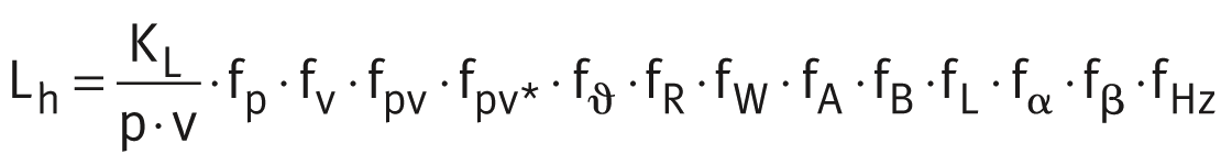
Bearings requiring maintenance
Rating life of bearings requiring maintenance: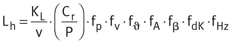 Rating life of bearings requiring maintenance taking account of correction factors for periodic relubrication, see link:
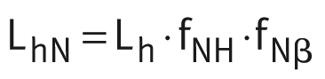
Conversion of rating life value
Conversion of the rating life from operating hours to revolutions: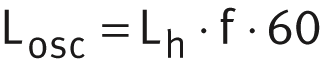
Conversion of the rating life for v < 0,001 m/s
For sliding velocities v < 0,001 m/s, at which the rating life must be calculated using v = 0,001 m/s, the rating life is converted from operating hours to revolutions as follows.For rotation:
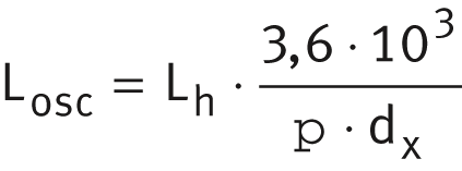 For swivelling:
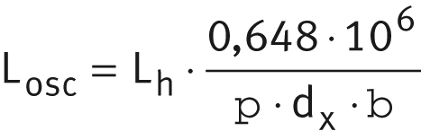
| dx | mm | Specific diameter, see table. |
Specific plain bearing factor
Sliding layer, sliding contact surface | Specific plain bearing factor KL |
|---|---|
E40, E40-B | 1 000 |
E50 | 2 500 |
ELGOGLIDE | 25 000 |
ELGOGLIDE-W11 | |
ELGOTEX | 7 000 |
PTFE composite | 1 000 |
PTFE film | 1 000 |
Steel/steel | 30 |
Steel/bronze | 2,3 |
Load and motion duty cycle
Where plain bearings are subjected to varying loads and motions, the rating life can be calculated in approximate terms. This requires data for the load, the motion and the corresponding proportional operating times (operating duration), ➤ Figure.
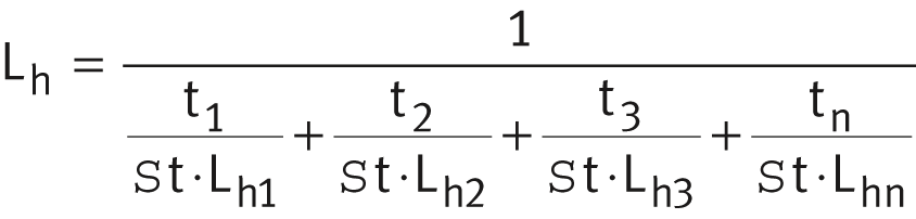
| Lh | h | Theoretical rating life taking account of variable conditions |
| t1, t2, ..., tn | h or % | Proportional duration of defined corresponding operating period |
| Σt | h or % | Total operating time (t1 + t2 + t3 ... tn) |
| Lh1, Lh2, ..., Lhn | h | Rating life for individual periods. |
Rating life for specified load and motion duty cycle

in accordance with calculation principle
Symbols, units and definitions
| Lh | h | Rating life of plain bearing |
| Losc | revolutions | Rating life in oscillations |
| LhN | h | Rating life with periodic relubrication |
| KL | Specific plain bearing factor | |
| p | N/mm2 | Specific load |
| v | m/s | Sliding velocity |
| Cr | N | Basic radial load rating |
| P | N | Equivalent bearing load |
| f | min–1 | Swivel frequency |
| fp | Correction factor for load | |
| fv | Correction factor for sliding velocity | |
| fpv | Correction factor for frictional energy | |
| fpv* | Correction factor for frictional energy for ELGOGLIDE and ELGOTEX | |
| fϑ | Correction factor for temperature | |
| fR | Correction factor for roughness depth | |
| fW | Correction factor for material | |
| fA | Correction factor for condition of rotation | |
| fB | Correction factor for width ratio | |
| fL | Correction factor for linear motion | |
| fα | Correction factor for tilt angle | |
| fβ | Correction factor for swivel and oscillation angle | |
| fHz | Correction factor for variable load | |
| fNH | Correction factor for relubrication, as a function of frequency | |
| fNβ | Correction factor for relubrication, as a function of β | |
| fdK | Correction factor for sphere diameter. |
Correction factors
In calculation of the basic rating life, numerous influences are taken into consideration for the specific bearing by means of correction factors, see link.
Preselection of correction factors
The correction factors are selected as a function of the sliding layer or the sliding contact surface and applied in the appropriate rating life equation, see tables.
The lists of the series also include the sealed variant with lip seals 2RS or high performance seals 2TS.
Maintenance-free and low-maintenance bushes, flanged bushes and thrust washers
Series | Sliding layer | Motion | Correction factors | ||||||||||||
|---|---|---|---|---|---|---|---|---|---|---|---|---|---|---|---|
fp | fv | fpv | fpv* | fϑ | fR | fW | fA | fB | fL | fα | fβ | fHz | |||
EGB EGF EGW | E50 | Rotary | ■ | ■ | ■ | ‒ | ■ | ■ | ‒ | ■ | ‒ | ‒ | ‒ | ‒ | ‒ |
E40 | ■ | ■ | ■ | ‒ | ■ | ■ | ■ | ■ | ‒ | ‒ | ‒ | ‒ | ‒ | ||
Linear | ■ | ■ | ■ | ‒ | ■ | ■ | ■ | ■ | ‒ | ■ | ‒ | ‒ | ‒ | ||
ZGB | ELGOGLIDE ELGOGLIDE-W11 | Rotary | ■ | ‒ | ‒ | ■ | ■ | ■ | ■ | ■ | ■ | ‒ | ‒ | ■ | ■ |
Linear | ■ | ‒ | ‒ | ■ | ■ | ■ | ■ | ■ | ‒ | ■ | ‒ | ‒ | ‒ | ||
ZWB | ELGOTEX | Rotary | ■ | ‒ | ‒ | ■ | ■ | ■ | ■ | ■ | ■ | ‒ | ‒ | ■ | ‒ |
Linear | ■ | ‒ | ‒ | ■ | ■ | ■ | ■ | ■ | ‒ | ■ | ‒ | ‒ | ‒ | ||
Maintenance-free spherical plain bearings and rod ends
Series | Sliding layer | Correction factors | |||||||||
|---|---|---|---|---|---|---|---|---|---|---|---|
Spherical plain bearing | Rod end | fp | fv | fpv | fpv* | fϑ | fA | fα | fβ | fHz | |
GE..-UK GE..-FW GE..-SW GE..-AW GE..-PW GE..-DW | GIR..-UK GAR..-UK GIKR..-PW GIKPR..-PW GAKR..-PW GIKSR..-PS GIKPSR..-PS GAKSR..-PS | ELGOGLIDE ELGOGLIDE-W11 | █ | ‒ | ‒ | █ | █ | █ | █ | █ | █ |
PTFE composite | █ | █ | █ | ‒ | █ | █ | ‒ | ‒ | █ | ||
PTFE film | █ | █ | █ | ‒ | █ | █ | ‒ | ‒ | █ | ||
Spherical plain bearings and rod ends requiring maintenance
Series | Sliding contact surface | Correction factors | |||||||
|---|---|---|---|---|---|---|---|---|---|
Spherical plain bearing | Rod end | fp | fv | fϑ | fA | fdK | fβ | fHz | |
GE..-DO GE..-HO GE..-FO GE..-ZO GE..-LO GE..-SX | GIR..-DO GIL..-DO GAR..-DO GAL..-DO GIHNRK..-LO GIHRK..-DO GK..-DO GF..-DO | Steel/steel | ■ | ■ | ■ | ■ | ■ | ■ | ■ |
GE..-PB | GIKR..-PB GIKL..-PB GAKR..-PB GAKL..-PB | Steel/bronze | ■ | ■ | ■ | ■ | ■ | ■ | ■ |
Legend
| ■ | The selected correction factor must be applied in the rating life equation. The value is determined from the diagrams and tables. |
Load fp and sliding velocity fv
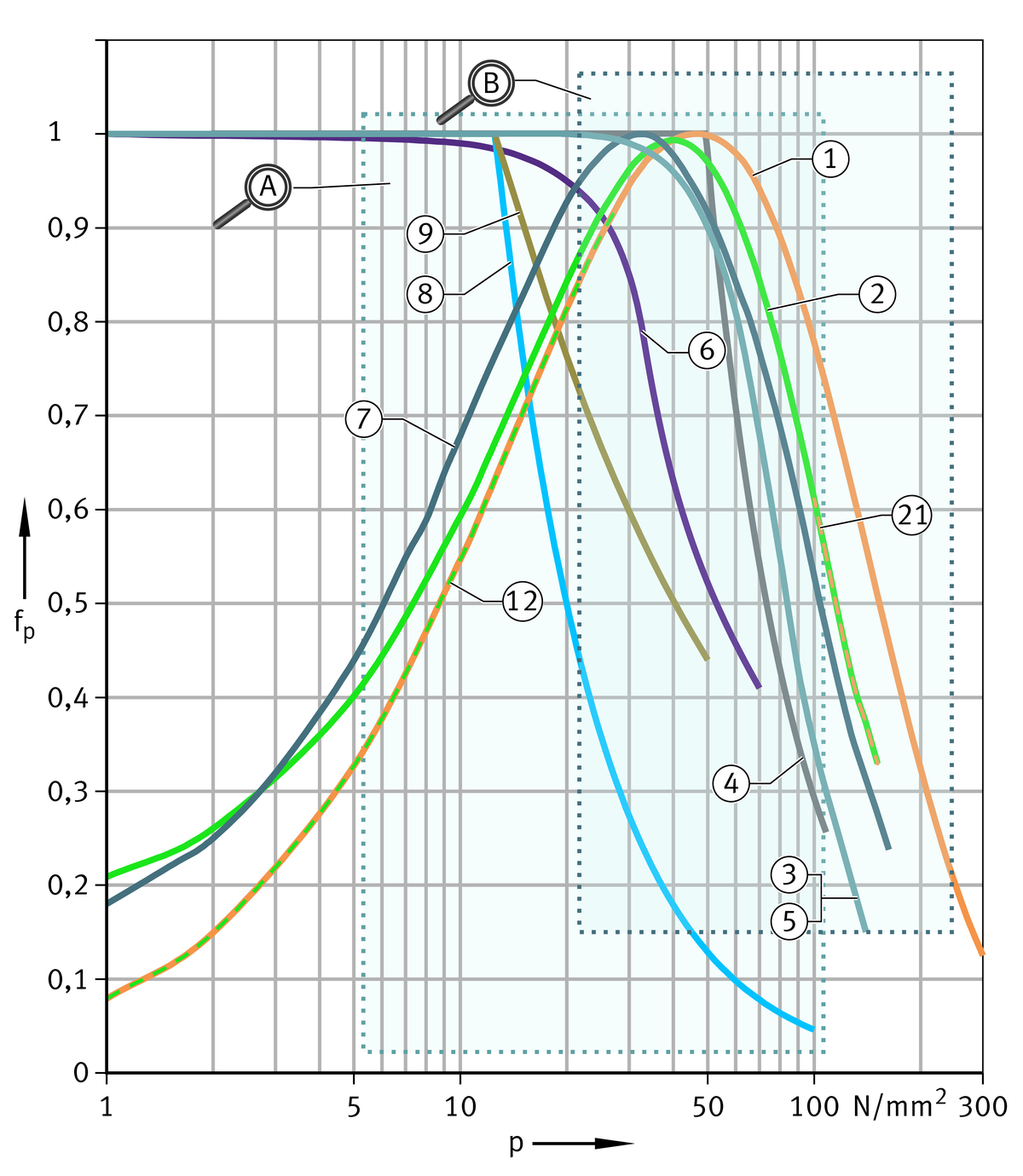
The values for the correction factor for load fp are shown in an overview diagram and two enlarged areas, ➤ Figure to ➤ Figure. The correction factor for sliding velocity fv can also be read from a diagram, ➤ Figure.
Correction factor for load, overview


Correction factor for load, requiring maintenance
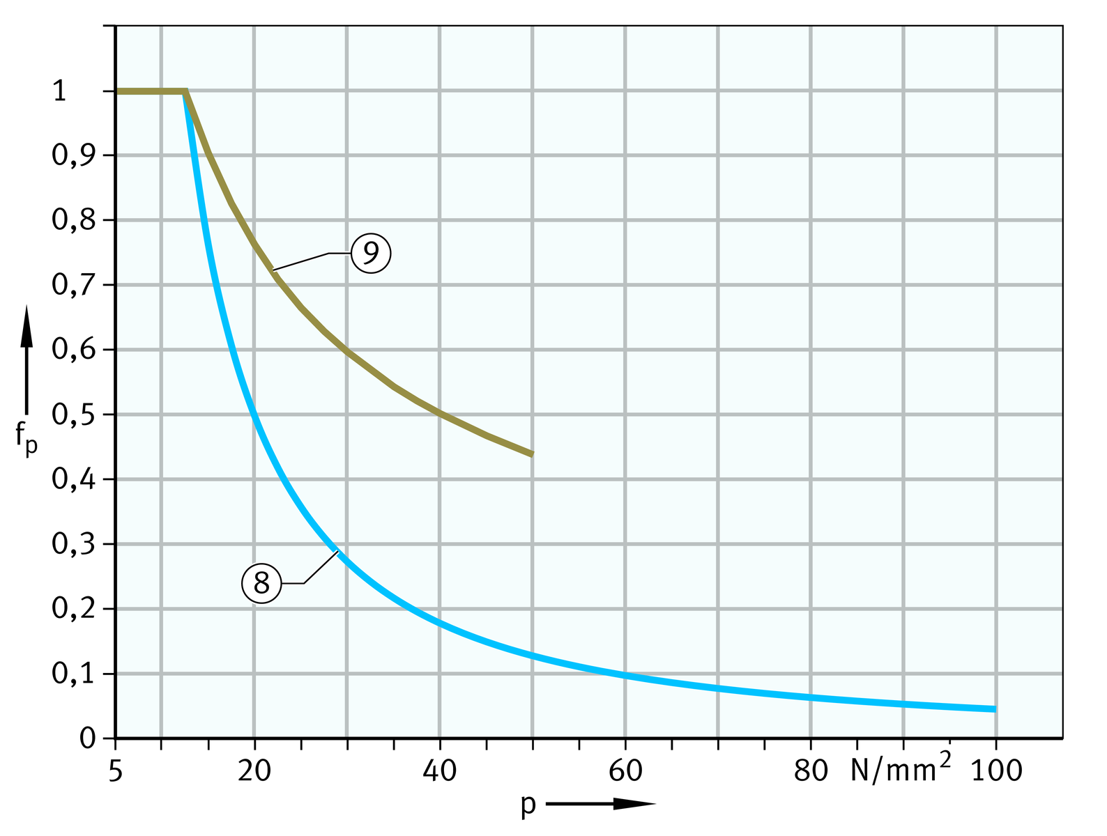
Correction factor for load, maintenance-free and low-maintenance
Correction factor
for sliding velocity
Frictional energy fpv
The correction factor fpv is derived from the product of the bearing load and the velocity, ➤ Figure. In the case of bearings with ELGOGLIDE or ELGOTEX, the relative specific frictional energy pv* is necessary, see ➤ equtions.
Correction factor for frictional energy
Relative specific frictional energy pv*
ELGOGLIDE and ELGOGLIDE-W11: ELGOTEX:
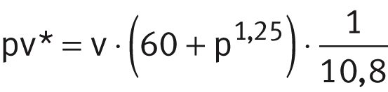
| pv* | Relative specific frictional energy | |
| p | N/mm2 | Specific load, for calculation see link |
| v | m/s | Sliding velocity, for calculation see link. |
ACHTUNG
An increasing pv or pv* value necessitates an increased level of heat dissipation. This must be ensured by means of the adjacent construction.
Temperature fϑ
The influence of temperature is taken into consideration in relating life calculation with the aid of the correction factor fϑ, ➤ Figure and table.
Correction factor for temperature for maintenance-free and low-maintenance bearings
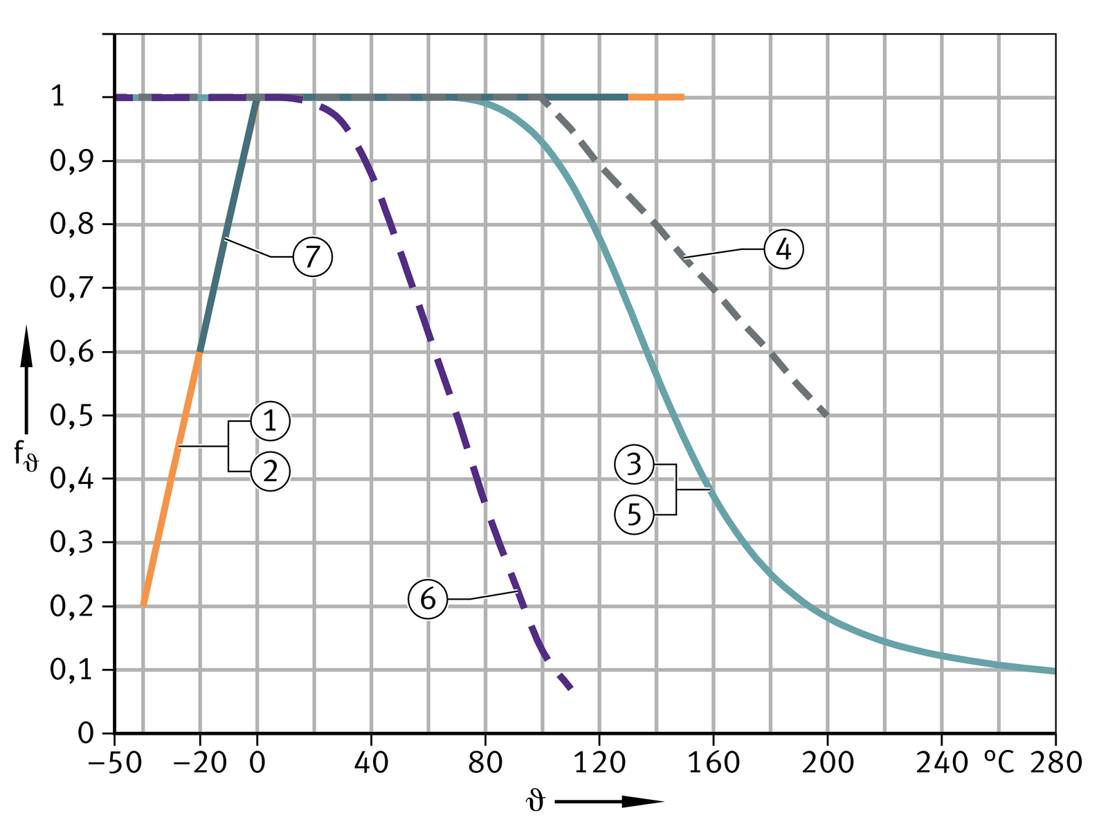
Correction factor fϑ for bearings requiring maintenance
Sliding contact surface | Operating temperature ϑ | |||
|---|---|---|---|---|
≦ 150 °C | 150 °C < ϑ ≦ 180 °C | 180 °C < ϑ ≦ 200 °C | 200 °C < ϑ ≦ 250 °C | |
Correction factor fϑ | ||||
Steel/steel | 1 | 0,9 | 0,7 | ‒ |
Steel/bronze | 1 | 0,9 | 0,8 | 0,5 |
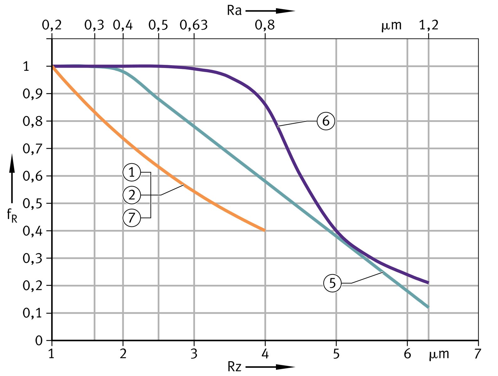
Roughness depth fR
In the case of spherical plain bearings and rod ends, a mating surface with the most suitable roughness depth is already provided by the inner ring. For bushes, flanged bushes and thrust washers, the correction factor for roughnesss depth fR must be taken into consideration, ➤ Figure.
Correction factor for roughness depth
Material fW
The correction factor fW is dependent on the material of the mating surface with a roughness depth Rz 2 to Rz 3, see table.
Correction factor fW
Mating surface material | Layer thickness | Correction factor fW | ||
|---|---|---|---|---|
E40 | ELGOGLIDE ELGOGLIDE-W11 ELGOTEX | |||
mm | ||||
Steel** | ||||
|
|
| ||
| Unalloyed | ‒ | 0,5 | ‒ |
Nitrided | ‒ | 0,5 | 1 | |
Corrosion-resistant | ‒ | 1 | 1 | |
Hard chromium coating (Durotect CMT) | ≧ 0,013 | 1 | 1 | |
Zinc plated | ≧ 0,013 | 0,1 | ‒ | |
Phosphated | ≧ 0,013 | 0,1 | ‒ | |
Flake graphite cast iron Rz 2 | ‒ | 0,5 | ‒ | |
Anodised aluminium | ‒ | 0,2 | ‒ | |
Hard anodised aluminium 450 + 50 HV | 0,025 | 1 | ‒ | |
Copper-based alloys | ‒ | 0,2 | ‒ | |
Nickel | ‒ | 0,1 | ‒ | |
**
For increased loads, the steel hardness should correspond to the following values:
in the case of E40, at least 25 HRC to 50 HRC | ||
| in the case of ELGOGLIDE and ELGOTEX, at least 55 HRC. |
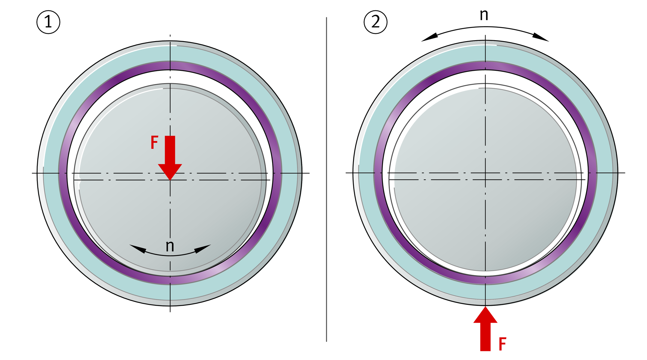
Condition of rotation fA
The correction factor fA is dependent on the type of bearing and the type of load, ➤ Figure:
- plain bushes, thrust washers:
- point load fA = 1 (rotating shaft, stationary bush)
- circumferential load fA = 2 (stationary shaft, rotating bush)
- thrust washer fA = 1
- linear motion fA = 1
- spherical plain bearings, rod ends:
- fA = 1.
Correction factor for condition of rotation
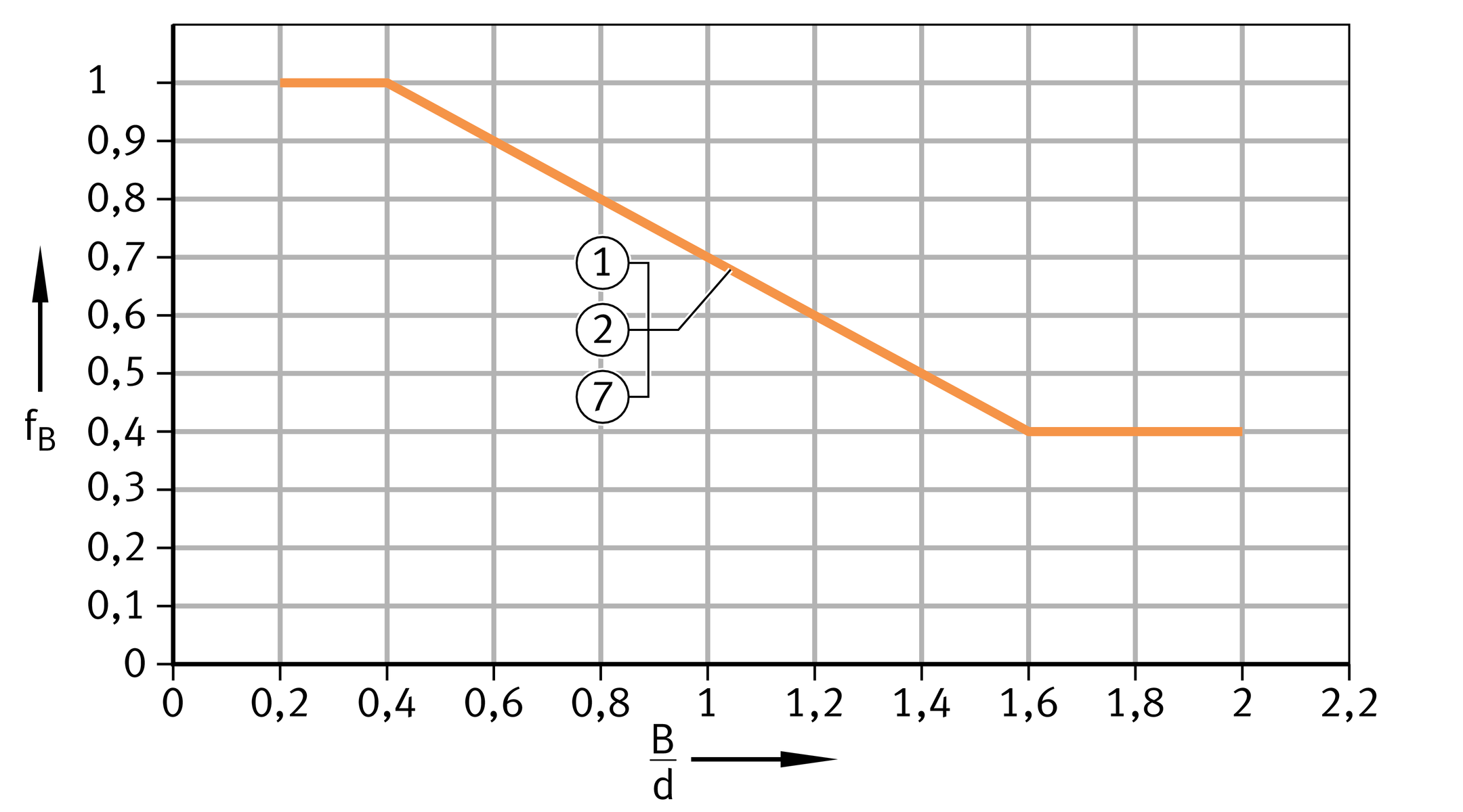
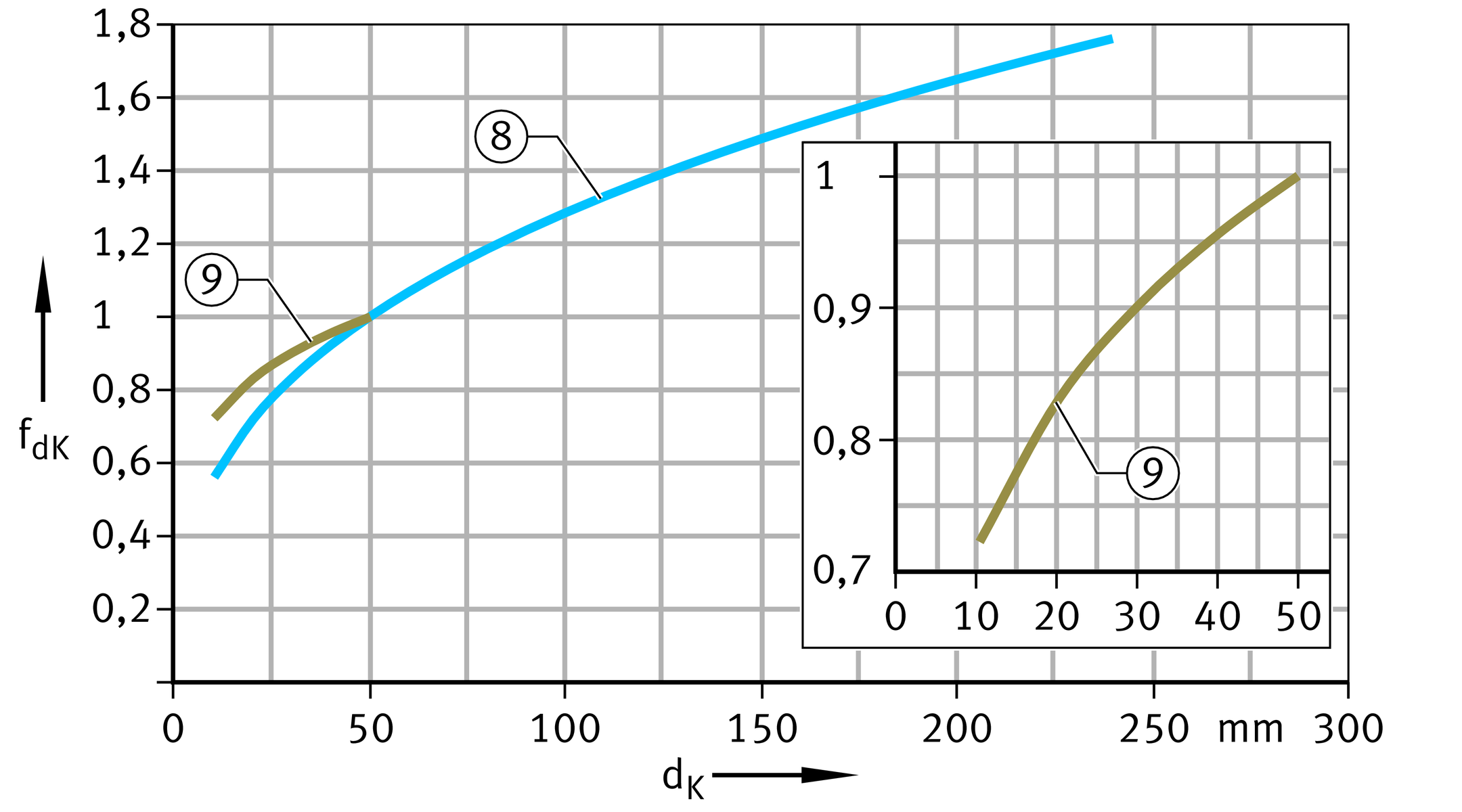
Width ratio fB and sphere diameter dK
The factors taken into consideration in rating life calculation are the width ratio in the case of maintenance-free plain bearings and the sphere diameter in the case of plain bearings requiring maintenance, ➤ Figure and ➤ Figure.
Correction factor for width ratio
Correction factor for sphere diameter
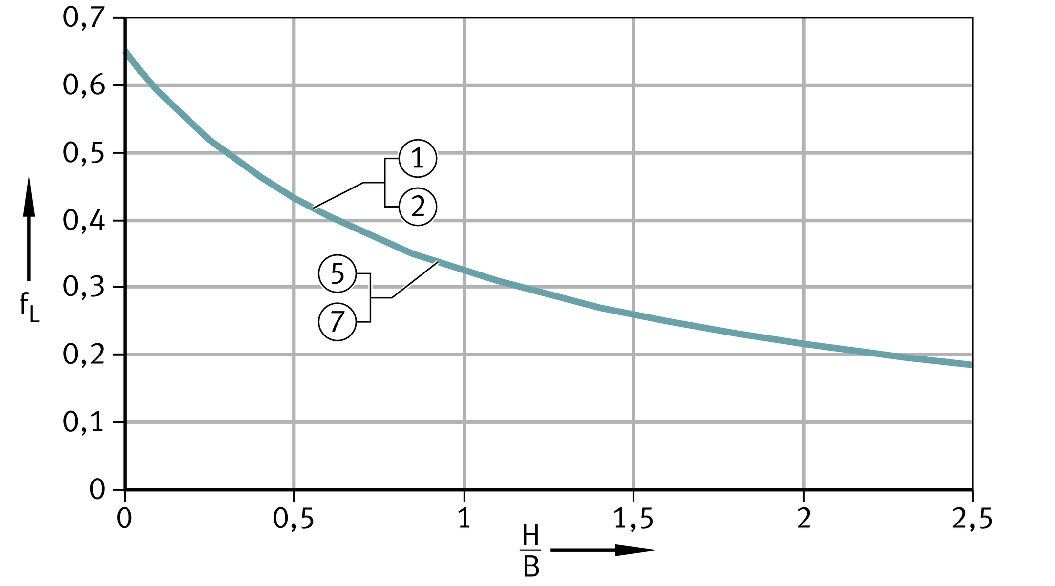
Linear motion fL
The correction factor fL is necessary in the case of linear motion with bushes with the sliding layer E40, ELGOGLIDE or ELGOTEX, ➤ Figure.
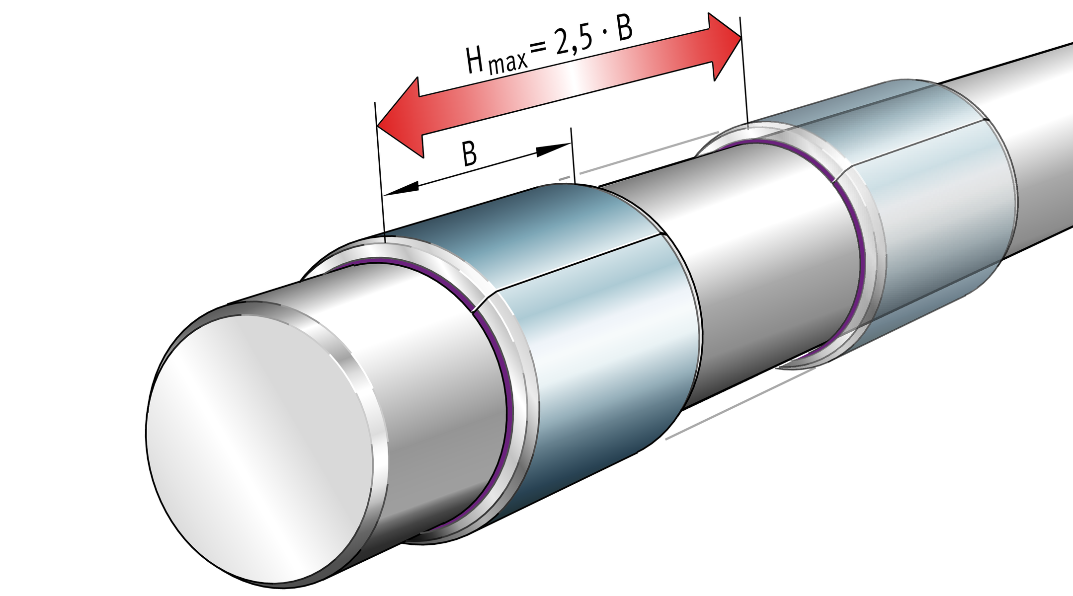
ACHTUNG
In the case of linear motion, the stroke length should not exceed the maximum stroke Hmax = 2,5 · B, ➤ Figure.
Correction factor for linear motion
Maximum stroke length in linear motion
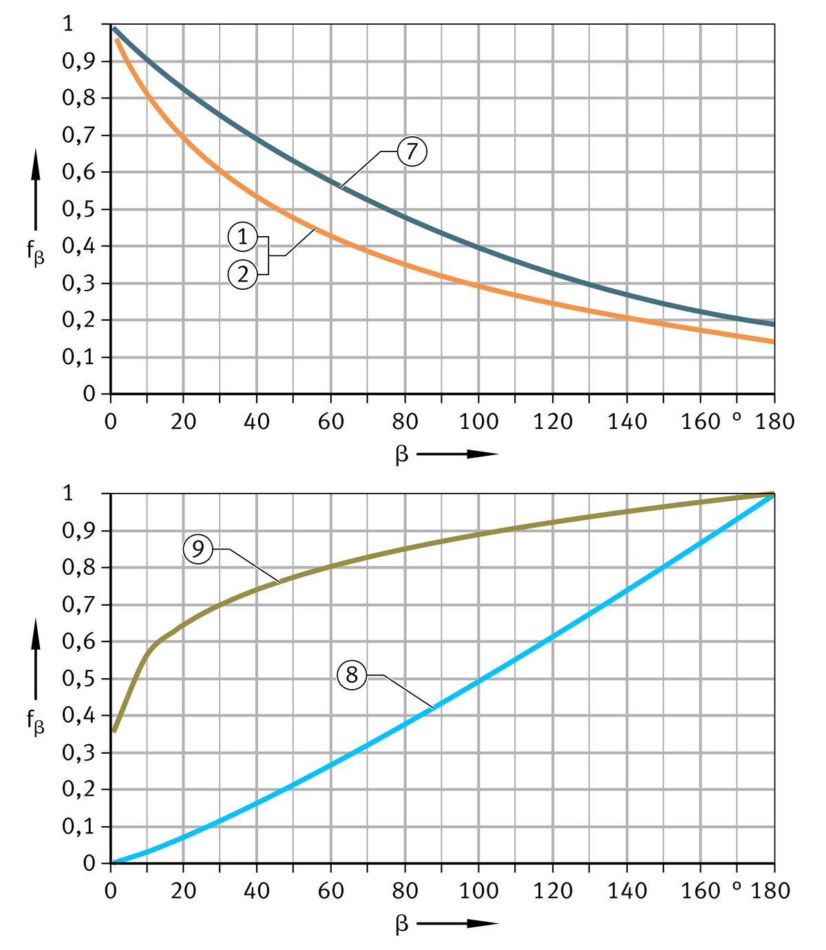
Tilt angle fα and swivel angle fβ
The tilt motions of spherical plain bearings are taken into consideration by the correction factor fα, while the swivel motions of spherical plain bearings or bushes are taken into consideration by the correction factor fβ, ➤ Figure and ➤ Figure.
ACHTUNG
In the case of swivel angles of ≧180° or rotation, the following applies:
- fβ = 0,15 for ELGOGLIDE
- fβ = 0,2 for ELGOTEX.
Correction factor for tilt angle
Correction factor for swivel and oscillation angle
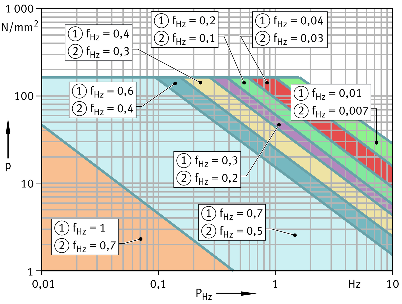
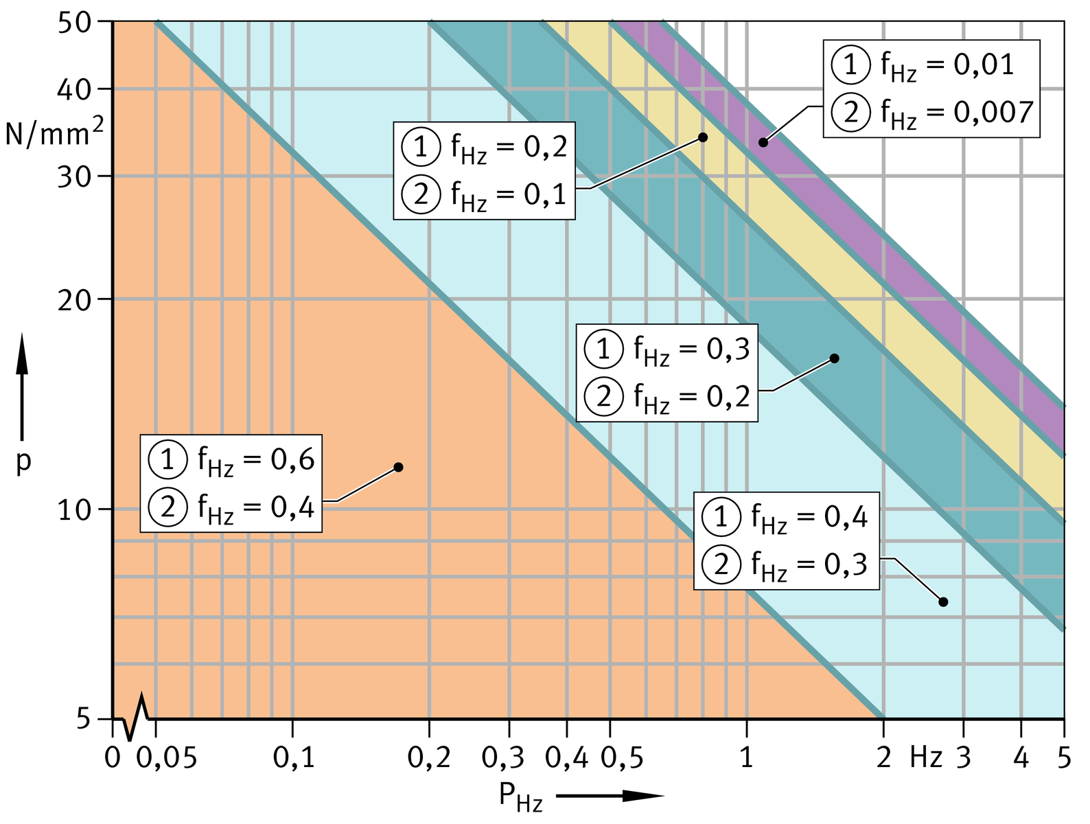
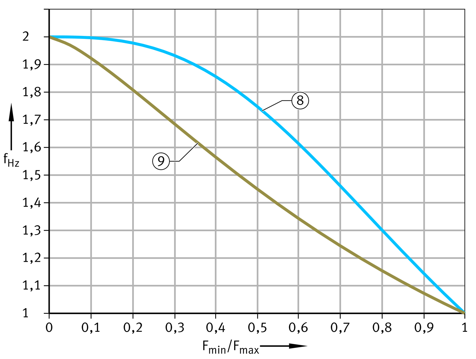
Variable load fHz
The correction factor for variable load fHz takes account of the influence of dynamic pulsating loads and dynamic alternating loads on the rating life. Loads that pass through the zero line in the Fr-t diagram are designated as alternating loads. Loads that are exclusively in the positive or negative region are designated as pulsating loads, see table.
The load frequency PHz (unit Hz) indicates the number of load cycles or load oscillations per second.
Type of load and correction factor fHz
Sliding layer, | Type of load | ||
|---|---|---|---|
Unilateral constant load | Alternating load | Pulsating load | |
|
|
| |
Correction factor fHz | |||
ELGOGLIDE | 1 | ||
ELGOGLIDE-W11 | |||
PTFE composite | |||
PTFE film | |||
Steel/steel | 2 | ||
Steel/bronze | 2 | ||


fHz values for ELGOGLIDE and ELGOGLIDE-W11 under alternating load and pulsating load
fHz values for PTFE composite under alternating load and pulsating load
fHz values for PTFE film under alternating load and pulsating load
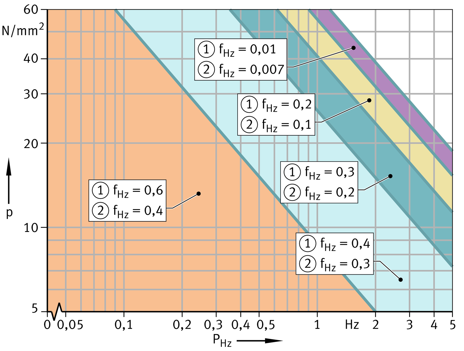
fHz values for steel/steel and steel/bronze under pulsating load
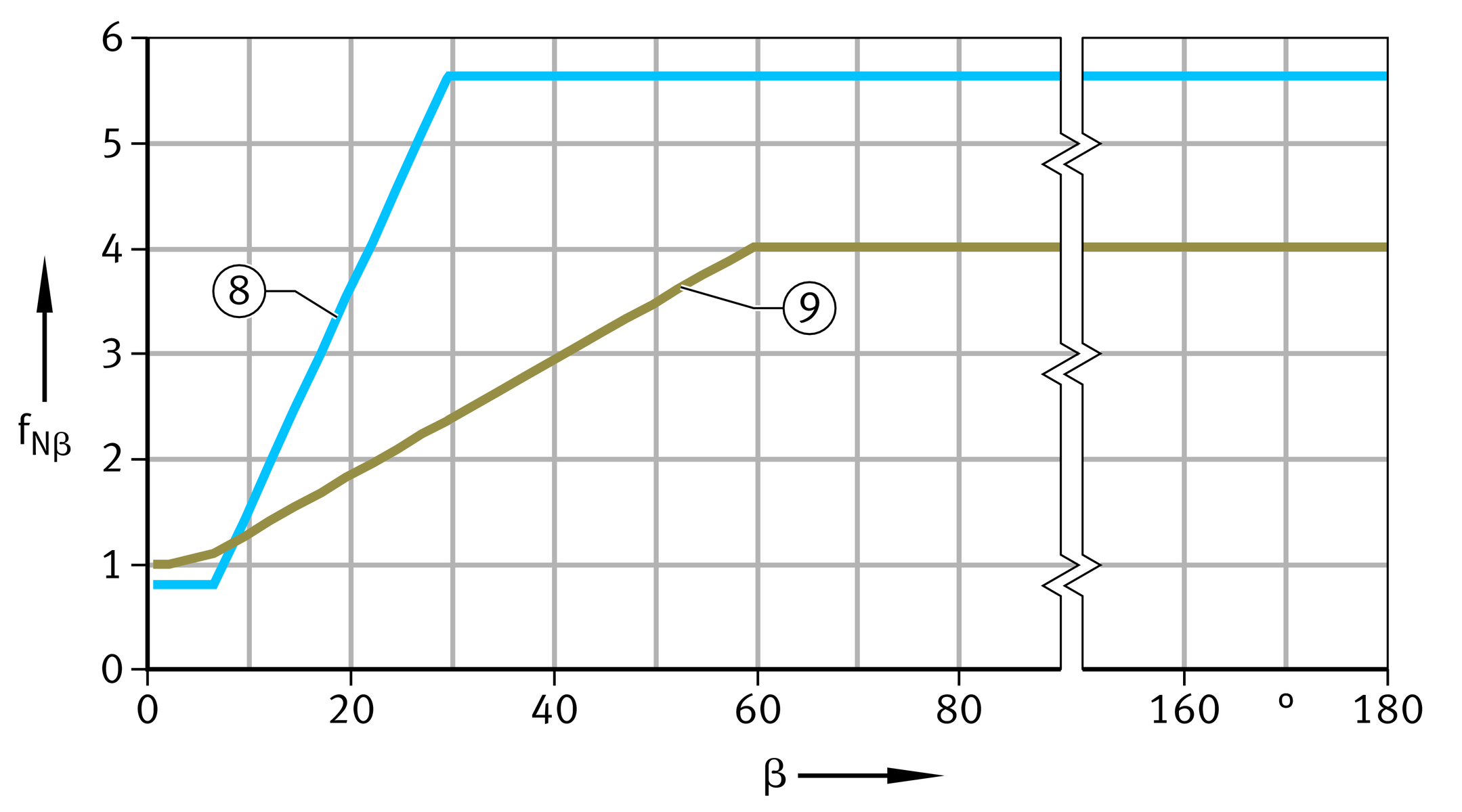
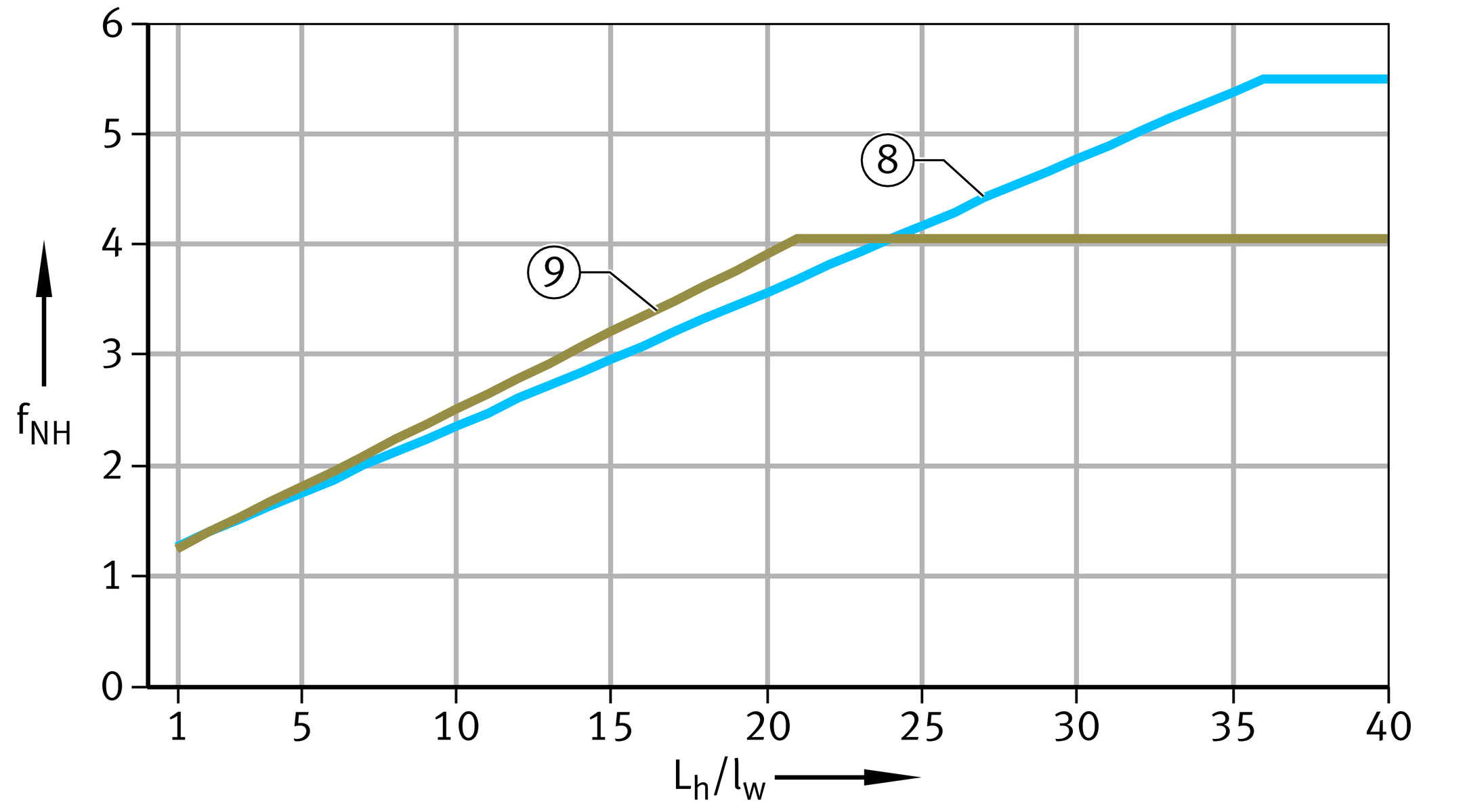
Relubrication fNH and fNβ
If periodic relubrication is carried out on spherical plain bearings requiring lubrication, their rating life can be increased. This is taken into consideration by means of a correction factor dependent on the frequency and by a factor dependent on the swivel angle β, ➤ Figure and ➤ Figure.
The relubrication interval for spherical plain bearings requiring lubrication must be no more than half the rating life: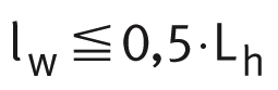
| lw | h | Relubrication interval |
| Lh | h | Basic rating life. |
Correction factor for relubrication, as a function of frequency
Correction factor for relubrication, as a function of β