
Load carrying capacity and life
The size of a linear ball bearing is determined by the demands made in terms of load carrying capacity, rating life and operational security.
The load carrying capacity is described in terms of:
- the basic dynamic load rating C
- the basic static load rating C0.
The calculation of the basic dynamic and static load ratings given in the dimension tables is based on DIN 636-1.
Basic rating life
The basic rating life L is reached or exceeded by 90 % of a sufficiently large group of apparently identical bearings before the first evidence of material fatigue occurs.


| L | m | Basic rating life L in 100 000 m |
| C | N | Basic dynamic load rating |
| P | N | Equivalent dynamic bearing load |
| Lh | h | Basic rating life in operating hours |
| H | m | Single stroke length |
| nosc | min–1 | Number of return strokes per minute |
 | m/min | Mean travel velocity. |
Operating life
The operating life is defined as the life actually achieved by a shaft guidance system. It may differ significantly from the calculated life.
The following influences can lead to premature failure through wear or fatigue:
- misalignment between the guideways and guidance elements
- contamination
- inadequate lubrication
- reciprocating motion with very small stroke length (false brinelling)
- vibration during stoppage (false brinelling).
Due to the wide variety of mounting and operating conditions, it is not possible to precisely predetermine the operating life of a shaft guidance system. The safest way to arrive at an appropriate estimate of the operating life is comparison with similar applications.
Static load safety factor
The static load safety factor S0 indicates the security against impermissible permanent deformations in the bearing and is determined by means of the following ➤ equation.
| S0 | Static load safety factor | |
| C0 | N | Basic static load rating |
| P0 | N | Equivalent static load. |
ACHTUNG
For linear ball bearings KH and KN..-B, the value must be S0 ≧ 4.
In relation to guidance accuracy and smooth running, a value of S0 ≧ 2 is regarded as permissible. If S0 < 2, please contact us.
Influence of the shaft raceway on the basic load ratings
The basic load ratings in the dimension tables are only valid if a ground (Ra 0,3) and hardened shaft (at least 670 HV) is provided as a raceway.
Differences in raceway hardness
If shafts with a surface hardness lower than 670 HV are used (for example, shafts made from X46 or X90), a hardness factor must be applied, see equations and ➤ Figure.


| CH | N | Effective dynamic load rating |
| fH | Dynamic hardness factor, ➤ Figure | |
| C | N | Basic dynamic load rating |
| C0H | N | Effective static load rating |
| fH0 | Static hardness factor, ➤ Figure | |
| C0 | N | Basic static load rating. |
Static and dynamic hardness factors for lower hardness of raceways


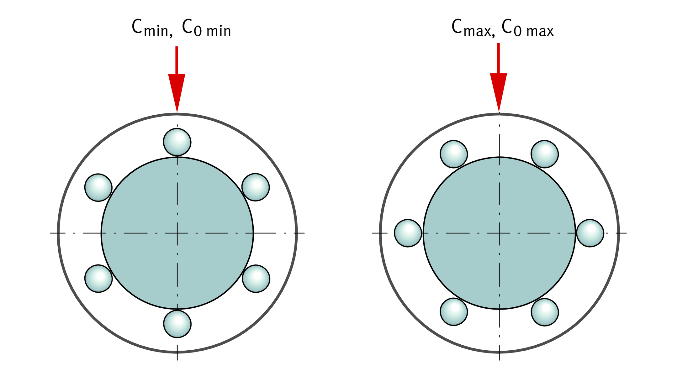
Load direction and orientation of the ball rows
The effective load rating of a linear ball bearing is dependent on the position of the load direction in relation to the position of the ball rows:
- The lowest load rating Cmin and C0 min occurs at the zenith position, ➤ Figure.
- The highest load rating Cmax and C0 max occurs at the symmetrical position, ➤ Figure.
If the bearings are mounted in correct alignment, the maximum load rating can be used. If aligned mounting is not possible or the direction of loading is not defined, the minimum load ratings must be assumed.
Main load direction
For linear ball bearings and linear ball bearing and housing units where the mounting position of the ball rows is defined, the basic load ratings C and C0 in the main load direction are given, ➤ Figure. For other load directions, the effective load ratings can be determined using the load direction factors in ➤ Figure, to ➤ Figure.
If the mounting position of the ball rows is not defined, the minimum basic load ratings are stated.
Load carrying capacity,
dependent on the position of the ball rows
Main load direction
for bearings and housing units

Linear ball bearings
The basic load ratings given in the dimension tables are defined as follows:
- For KH, KN..-B, KS, KB and KBS, the minimum and maximum load ratings apply, ➤ Figure.
- For KNO..-B, KSO and KBO, the basic load ratings apply in the main load direction. In the case of other load directions, see ➤ Figure, to ➤ Figure.
Linear ball bearing and housing units
The basic load ratings given in the dimension tables are defined as follows:
Compact range
For the units KGHK, KTHK, the minimum load rating applies.
Heavy duty range
For the heavy duty range, the basic load rating applies in the main load direction. In the case of other load directions, see ➤ Figure to ➤ Figure.
Machined range
For the units KGB, KGBA, KTB, KGBS, KGBAS, the minimum load rating applies.
For the open units KGBO, KGBAO, the basic load rating applies in the main load direction. In the case of other load directions, see ➤ Figure to ➤ Figure.
Load direction factors
The factors in ➤ Figure, to ➤ Figure, are applied as follows:
| Cw | N | Effective dynamic load carrying capacity |
| fS | Dynamic load factor for load direction | |
| C | N | Basic dynamic load rating. |

| C0w | N | Effective static load carrying capacity |
| fS0 | Static load factor for load direction | |
| C0 | N | Basic static load rating. |
Compact range
Load direction factor for KH06, KH08, KH10

Compact range
Load direction factor for KH12, KH14, KH16

Compact range
Load direction factor for KH20, KH25

Compact range
Load direction factor for KH30

Compact range
Load direction factor for KH40

Compact range
Load direction factor for KH50

Light range
Load direction factor for KN12-B, KN16-B

Light range
Load direction factor for KN20-B, KN25-B, KN30-B, KN40-B, KN50-B

Light range
Load direction factor for KNO12-B, KNO16-B

Light range
Load direction factor for KNO20-B, KNO25-B, KNO30-B, KNO40-B, KNO50-B

Heavy duty range
Load direction factor for KS12, KS16, KS20, KS25, KS30, KS40, KS50

Heavy duty range
Load direction factor for KSO12, KSO16

Heavy duty range
Load direction factor for KSO20, KSO25

Heavy duty range
Load direction factor for KSO30, KSO40, KSO50

Machined range
Load direction factor for KB12, KB16

Machined range
Load direction factor for KB20, KB25, KB30, KB40, KB50

Machined range
Load direction factor for KBO12, KBO16

Machined range
Load direction factor for KBO20, KBO25, KBO30, KBO40, KBO50

Misalignment of the shaft
Misalignment of the shaft impairs the running quality and operating life of linear ball bearings. Guidance systems with one shaft should therefore have at least two bearings, while guidance systems with two shafts should have at least three bearings.
Load factors in misalignment
Due to shaft flexing, it is not always possible to avoid misalignment, ➤ Figure. If it is present, load factors for misalignment should be applied, ➤ Figure and ➤ Figure.


| P, P0 | N | Equivalent dynamic or static load |
| KF, KF0 | Dynamic or static load factor for misalignment, ➤ Figure or ➤ Figure | |
| Fr | N | Maximum radial bearing load |
| C, C0 | N | Basic radial dynamic or static load rating, ➤ Figure or ➤ Figure. |
Misalignment φ of the shaft

Dynamic load factor for shaft misalignment

Static load factor
for shaft misalignment

Compensation of misalignments in the light and heavy duty range
Linear ball bearings KN..-B, KNO..-B, KS and KSO and linear ball bearing and housing units containing these bearings are self-aligning. They can compensate misalignments of up to ±30 angular minutes (KN..-B and KNO..-B) or ±40 angular minutes (KS and KSO) without detrimental effect on the load carrying capacity.