Linear recirculating roller bearing and guideway assemblies
Features
Linear recirculating roller bearing and guideway assemblies are used in applications with very high loads and very high requirements for rigidity and precision.
These preloaded units for long, unlimited stroke lengths are particularly suitable for use in machine tools.
A guidance system comprises at least one carriage, one guideway, one dummy guideway, plastic closing plugs and one mounting set per carriage.
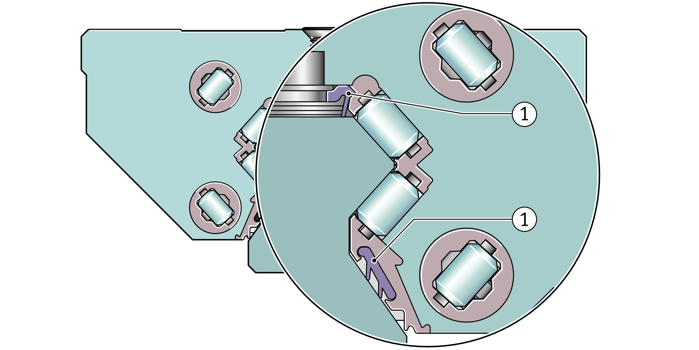
Full complement
Since they have the maximum possible number of rolling elements, full complement guidance systems have extremely high load carrying capacity and particularly high rigidity.
Carriages
The carriages have saddle plates made from hardened steel and the rolling element raceways are precision ground. The cylindrical rollers are recirculated in enclosed channels with plastic return elements.
Guideways
The guideways are made from hardened steel and are ground on all faces, the rolling element raceways are precision ground.
Location from above or below
Guideways TSX..-E ( -ADB , -ADK ) and TSX25-D ( -ADB , -ADK ) are located from above and have through holes with counterbores for the fixing screws. Guideways TSX..-E-U and TSX25-D-U are located from below and have threaded blind holes.
Slot for covering strip
Guideways TSX..-E-ADB and TSX25-D-ADB have a slot for the adhesive bonded steel covering strip ADB, while guideways TSX..-E-ADK and TSX25-D-ADK have a slot with undercut for the clip fit steel covering strip ADK.
Multi-piece guideways
If the required guideway length lmax is greater than the value in the dimension tables, the guideways are supplied in several segments, see link.
Standard accessories
The scope of delivery includes various accessory parts as standard.
Dummy guideway
The dummy guideway prevents damage to the rolling element set and prevents the rolling elements from falling out while the carriage is separated from the guideway.
Carriages are always pushed directly from the guideway onto the dummy guideway and must remain there until they are remounted.
Plastic closing plugs
The closing plugs close off the counterbores of the guideway holes flush with the surface of the guideway.
Optionally, two-piece plastic plugs and closing plugs made from brass or steel are also available.
Mounting set M-Satz
The delivery of RUE..-E includes the mounting set M-Satz. This comprises:
- one lubrication connector for grease lubrication
- O rings for sealing purposes if relubrication is carried out from above via the adjacent construction
- grub screws for closing off the relubrication hole from above.
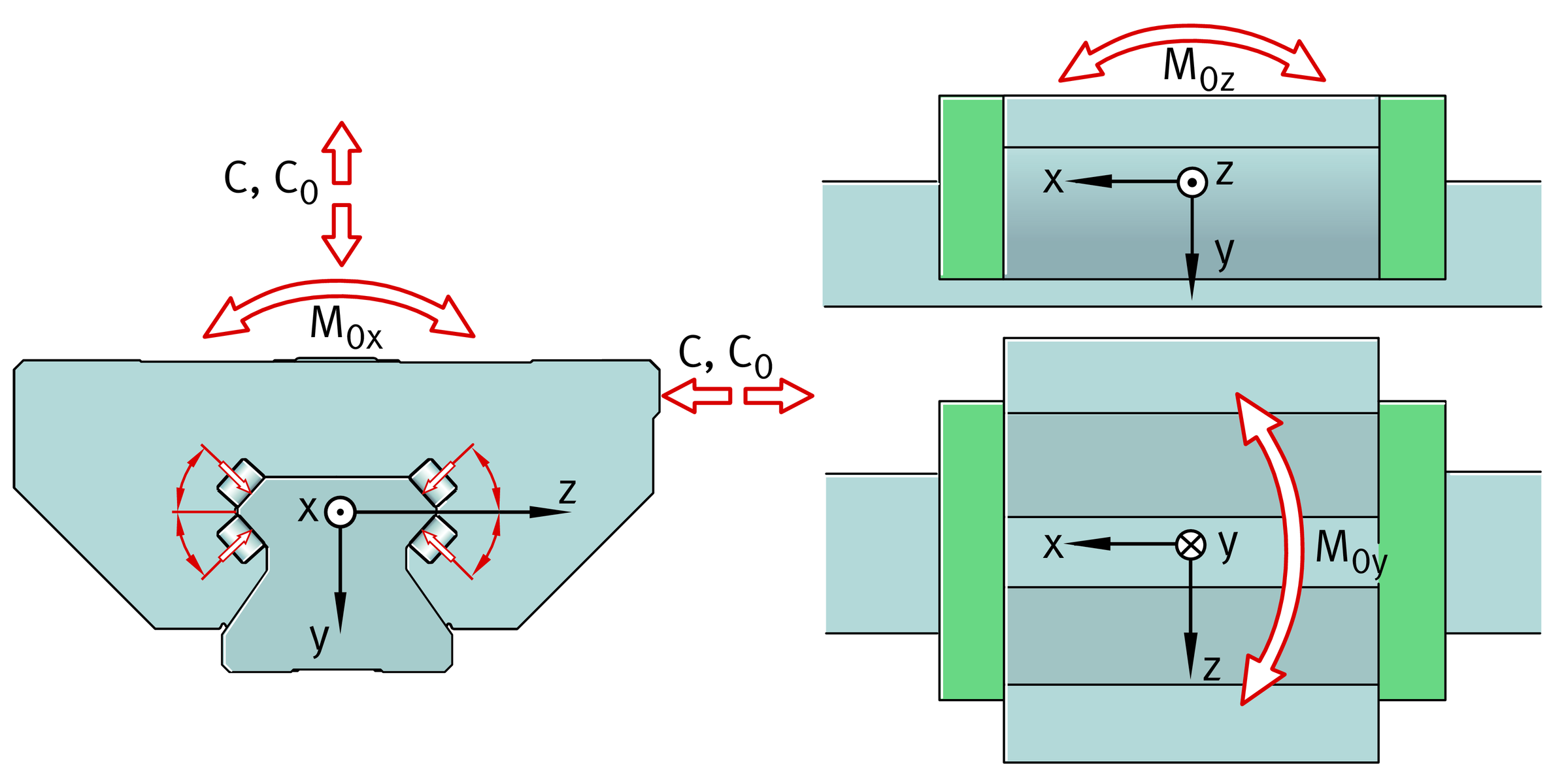
Load carrying capacity
The cylindrical rollers are in an X arrangement on the raceways.
The units can support loads from all directions, except in the direction of motion, and moments about all axes.
Load carrying capacity and contact angle
Acceleration and velocity
Linear recirculating roller bearing and guideway assemblies RUE..-E permit accelerations up to 100 m/s2 and velocities up to 4 m/s, see table.
Operating limits
Designation | Acceleration** up to | Travel velocity** up to |
|---|---|---|
m/s2 | m/s | |
RUE25-E | 100 | 3 |
RUE35-E | 100 | 4 |
RUE45-E | 100 | 3,5 |
RUE55-E | 100 | 3 |
RUE65-E | 50 | 2,5 |
RUE100-E | 5 | 1,5 |
**The values apply, within each size, for all available carriages.
Interchangeability
The interchangeability of carriages and guideways is dependent on the accuracy class and the size, see table. Interchangeability as required is valid only for the accuracy classes G2 and G3. When ordering individual components in the accuracy classes G0 and G1 the following postscript must be added to the order: “Interchangeable as required”.
Interchangeability of carriages and guideways
Designation | Carriage | Guideway |
|---|---|---|
RUE25-E | as required | as required |
RUE35-E | as required | as required |
RUE45-E | as required | as required |
RUE55-E | as required | as required |
RUE65-E** | restricted | restricted |
RUE100-E** | restricted | restricted |
**Where the carriages are interchangeable, this applies within one bearing size irrespective of the design of the carriage.
**If necessary, please contact us.
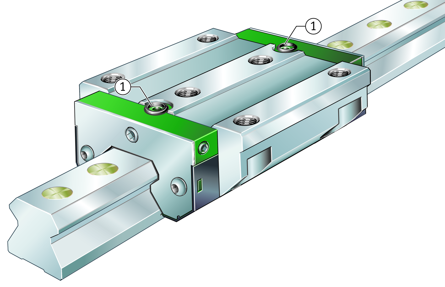
Sealing
The end pieces of the carriages are fitted on both sides with non-contact, corrosion-resistant end plates and elastic end wipers that retain the lubricant in the system.
Standard sealing strips ensure reliable sealing and protect the rolling element system against contamination, even in critical environmental conditions, ➤ Figure.
ACHTUNG
Under extremely heavy contamination load, additional wipers can be fitted. Where necessary, additional covers must be used.
Upper and lower sealing strips

Lubrication
Linear recirculating roller bearing and guideway assemblies RUE..-E are suitable for oil and grease lubrication. A lubrication connector for grease is included in the mounting set M-Satz with the delivery. Optionally, other lubrication connectors are available. Lubrication is optimised by accessories such as lubricant quantity metering valves (SMDS), long term lubrication units (KIT series 400) and the lubricant quantity metering unit (KIT series 500).
In the case of size 35 to 100, the lubrication connectors can be screw mounted into the end piece on the left, right or end face, while this is only possible on the end face in the case of size 25. The relubrication holes in the end faces and the sides are closed off by means of grub screws. Before the lubrication connector is screwed in, the corresponding grub screw must be removed. In the case of RUE100-E-L, an area of flash must be pierced using a hot pointed object, in accordance with the mounting manual MON 30.
ACHTUNG
If relubrication is carried out from above, it must be ensured that the adjacent construction completely covers the carriage (including the end pieces) and the O rings for sealing off the relubrication hole from above are inserted, ➤ Figure. Otherwise, lubricant may escape through the upper lubrication hole.
If the upper relubrication holes are not used, these can be closed off using grub screws. Grub screws GSTI for closing off the upper relubrication hole are included with the mounting set M-Satz.
Relubrication hole
ACHTUNG
If lubrication connectors are fitted on the end or side, the maximum permissible screw depth must be observed. If additional sealing elements KIT are used, the screw depth is increased for the end relubrication facility. The standard lubrication connector is then no longer usable. Suitable lubrication connectors must additionally be taken into consideration when ordering.
Operating temperature
As standard, linear recirculating roller bearing and guideway assemblies can be used at operating temperatures from –10 °C to +80 °C.
Corrosion-resistant design
Linear recirculating roller bearing and guideway assemblies RUE..-E are also available in the accuracy class G2 and preload class V3 in a corrosion-resistant design with the special coatings Corrotect and Protect A.
Design and safety guidelines
Preload
Linear recirculating roller bearing and guideway assemblies are available in the preload classes V1 to V5, see table.
Optimum rigidity of the elements is impaired by any deviation in the preload force. Linear recirculating roller bearing and guideway assemblies are therefore supplied as a preassembled unit; this means that the elements are sorted and matched to each other.
For interchangeability of the guideway and carriage, see link .
Preload class
Preload class | Preload setting |
|---|---|
V1 | 0,04 · C |
V2 | 0,08 · C |
V3** | 0,1 · C |
V4 | 0,13 · C |
V5 | 0,15 · C |
**Standard preload class.
Influence of preload on the linear guidance system
The preload of a linear guidance system defines the rigidity of the system. The linear recirculating roller bearing and guideway assembly RUE..-E can be obtained in the preload classes V1 to V5, where the preload class V3 is the standard preload class. This preload class can be used in numerous applications (including machine tools). If special requirements are present, the alternative preload classes may be used.
Increasing the preload increases the rigidity of the guidance system. The preload influences not only the rigidity but also the displacement force of the guidance system. The higher the preload, the larger the displacement force. Furthermore, preload also influences the operating life of the guidance system.
Friction
The coefficient of friction is dependent on the ratio C/P, see table.
Coefficient of friction
Load C/P | Coefficient of friction μRUE | ||
|---|---|---|---|
from | to | from | to |
4 | 20 | 0,002 | 0,004 |
Rigidity
The deflection curves show the deformation of the linear recirculating roller bearing and guideway assemblies including the deformation of the screw connections to the adjacent construction.
ACHTUNG
The rigidity curves are valid only for screw mounting in accordance with the mounting manual MON 30 and the standard preload class V3.
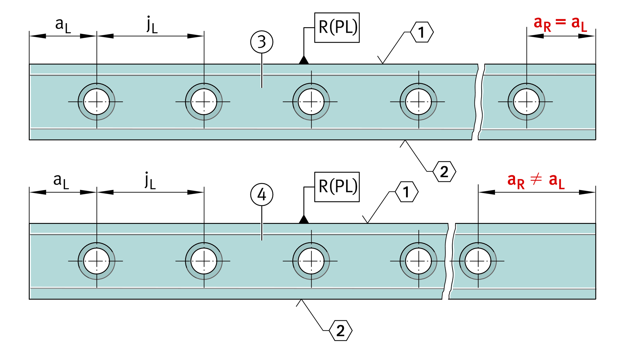
Hole patterns of guideways
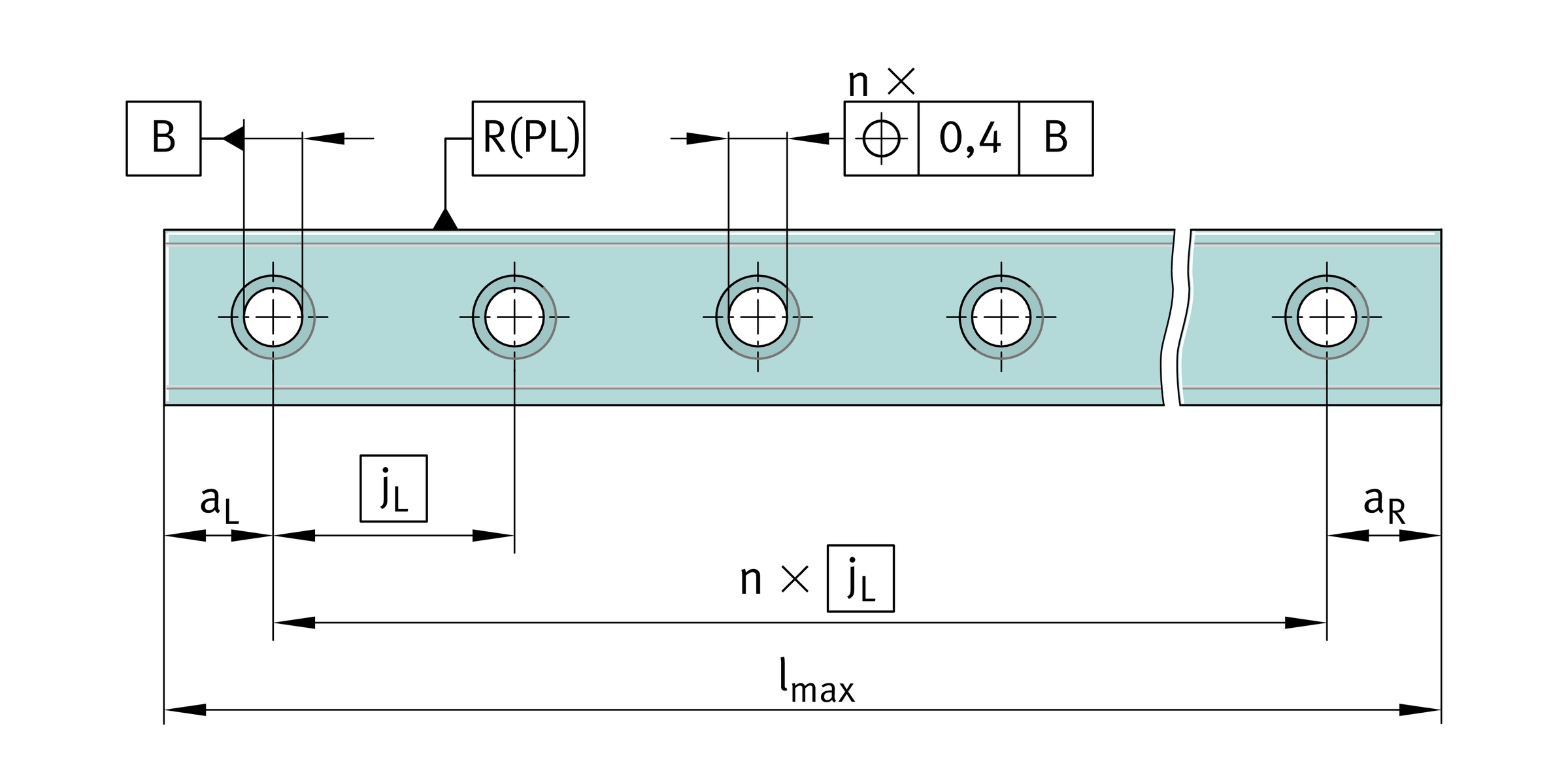
Unless specified otherwise, the guideways have a symmetrical hole pattern where aL = aR, ➤ Figure.
An asymmetrical hole pattern may also be available upon request. In this case, aL ≧ aL min and aR ≧ aR min, ➤ Figure.
ACHTUNG
Irrespective of the orientation of the locating face, aL is on the left and aR on the right, ➤ Figure. When ordering, the required orientation of the locating face (top or bottom) must be indicated.
Hole patterns of guideways with one row of holes


Maximum number of pitches between holes
The number of pitches between holes is the whole number equivalent to: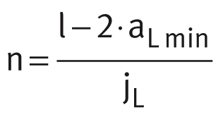 The spacings aL and aR are generally determined as follows:
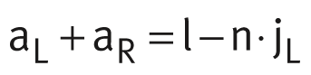 For guideways with a symmetrical hole pattern:
 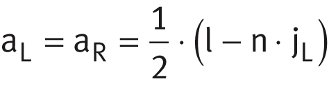 Number of holes:
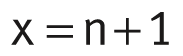
| aL, aR | mm | Spacing between start or end of guideway and nearest hole |
| aL min, aR min | mm | Minimum values for aL, aR |
| l | mm | Guideway length |
| n | – | Maximum possible number of pitches between holes |
| jL | mm | Spacing between holes |
| x | – | Number of holes. |
ACHTUNG
If the minimum values for aL and aR are not observed, the counterbores of the holes may be intersected. Risk of injury.
Multi-piece guideways
If the guideway length required is greater than lmax or joined guideways are required, these guideways are made up from segments that together comprise the total required length. The segments are matched to each other and marked. The pitch is always located centrally between the fixing holes.
Marking of multi-piece guideways
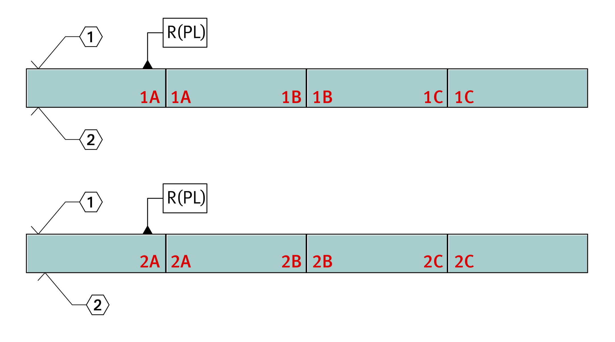
1A, 1A 1B, 1B 1C, 1C
2A, 2A 2B, 2B 2C, 2C
ACHTUNG
In the case of multi-piece guideways, the gap at the end faces between two segments must be < 0,05 mm.
Guideways suitable for joining as required
If partial guideway lengths (l < lmax) are to be combined with each other to form a guideway set as requested by the customer, the following postscript must be added to the order for the relevant guideway segment: “Guideway suitable for joining as required”.
If the guideway segment is an end segment, it is recommended that the guideway end has a chamfer, in order to make it easier to slide the carriages onto the guideway and protect the seals against damage. In this case, the position of the chamfer (left or right) and the position of the locating face (top or bottom) must be taken into consideration when ordering.
This design facilitates easier logistics.
Demands on the adjacent construction
The running accuracy is essentially dependent on the straightness, accuracy and rigidity of the fit and mounting surfaces.
The straightness of the system can be achieved most easily when the guideway is pressed against a locating face.
If the guideway cannot be aligned as recommended by means of locating faces or very high requirements are placed on the running accuracy, the guideway straightness must be restricted. The following postscript must be added to the order: “Restricted guideway straightness”.
Geometrical and positional accuracy of the adjacent surfaces
The higher the requirements for accuracy and smooth running of the guidance system, the more attention must be paid to the geometrical and positional accuracy of the mounting surfaces.
ACHTUNG
Tolerances of mounting surfaces and parallelism of mounted guideways must be observed, ➤ Figure, and table.
Surfaces should be ground or precision milled with the objective of achieving a mean roughness value Ramax 1,6.
Any deviations from the stated tolerances will impair the overall accuracy, alter the preload and reduce the operating life of the guidance system.
Height difference ΔH
For ΔH, permissible values are in accordance with the following equation.
| ΔH | μm | Maximum permissible deviation from the theoretically precise position, |
| a | – | Factor, as a function of the preload class, see table |
| b | mm | Centre distances between guidance elements. |
Factor a
Preload class | Factor a |
|---|---|
V1 | 0,15 |
V2 | 0,09 |
V3** | 0,075 |
V4 | 0,06 |
V5 | 0,06 |
**Standard preload class.
ACHTUNG
Observe the guidelines in the mounting manual MON 30 for RUE.
Tolerances of mounting surfaces and parallelism of mounted guideways and carriages
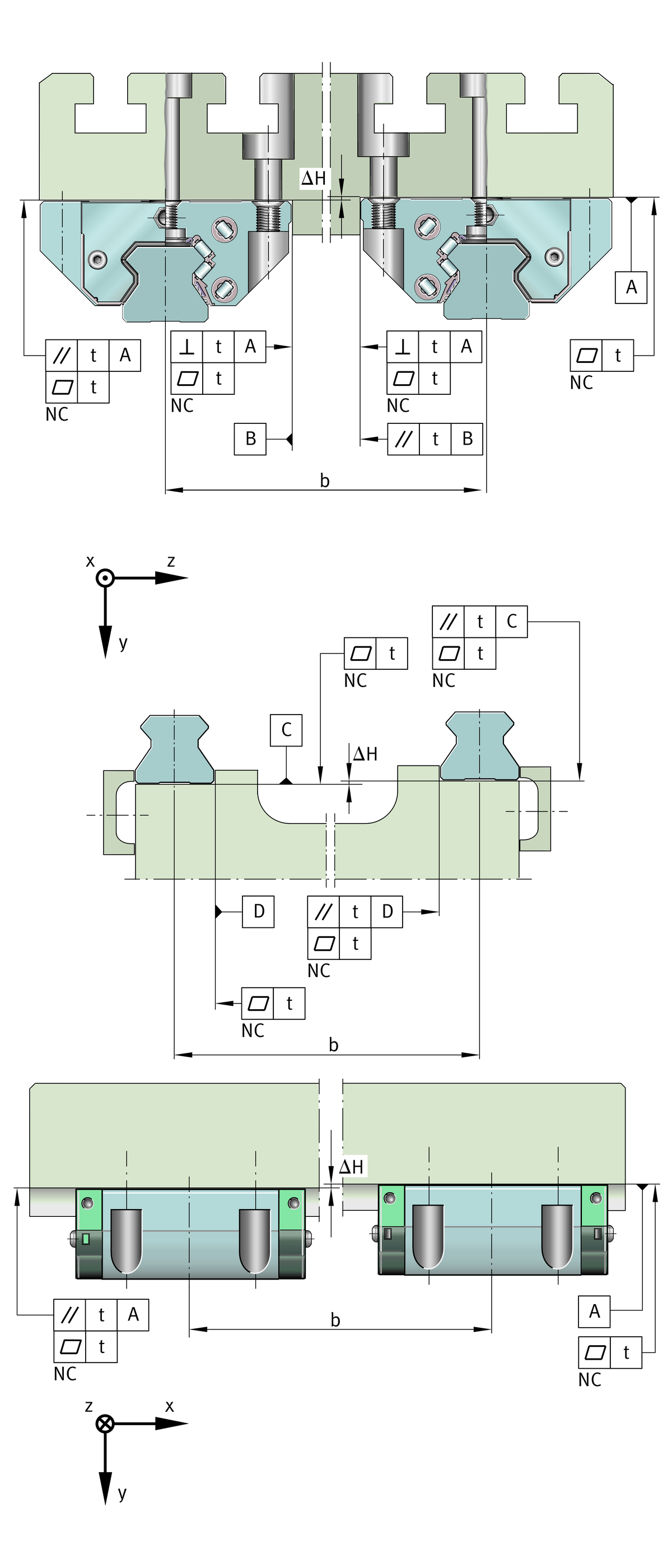
Parallelism of mounted guideways
For guideways arranged in parallel, the values for t are in accordance with➤ Figure and the table. If the maximum values are used, this may increase the displacement resistance.
Values for geometry and position
Guideway | Preload class | |
|---|---|---|
V1, V2 | V3**, V4, V5 | |
Parallelism, flatness and perpendicularity t | ||
μm | ||
TSX25-D (-U, -ADB, -ADK) | 11 | 7 |
TSX35-E (-U, -ADB, -ADK) | 15 | 10 |
TSX45-E (-U, -ADB, -ADK) | 17 | 10 |
TSX55-E (-U, -ADB, -ADK) | 20 | 10 |
TSX65-E (-U, -ADB, -ADK) | 20 | 10 |
TSX100-E | 20 | 10 |
**Standard preload class.
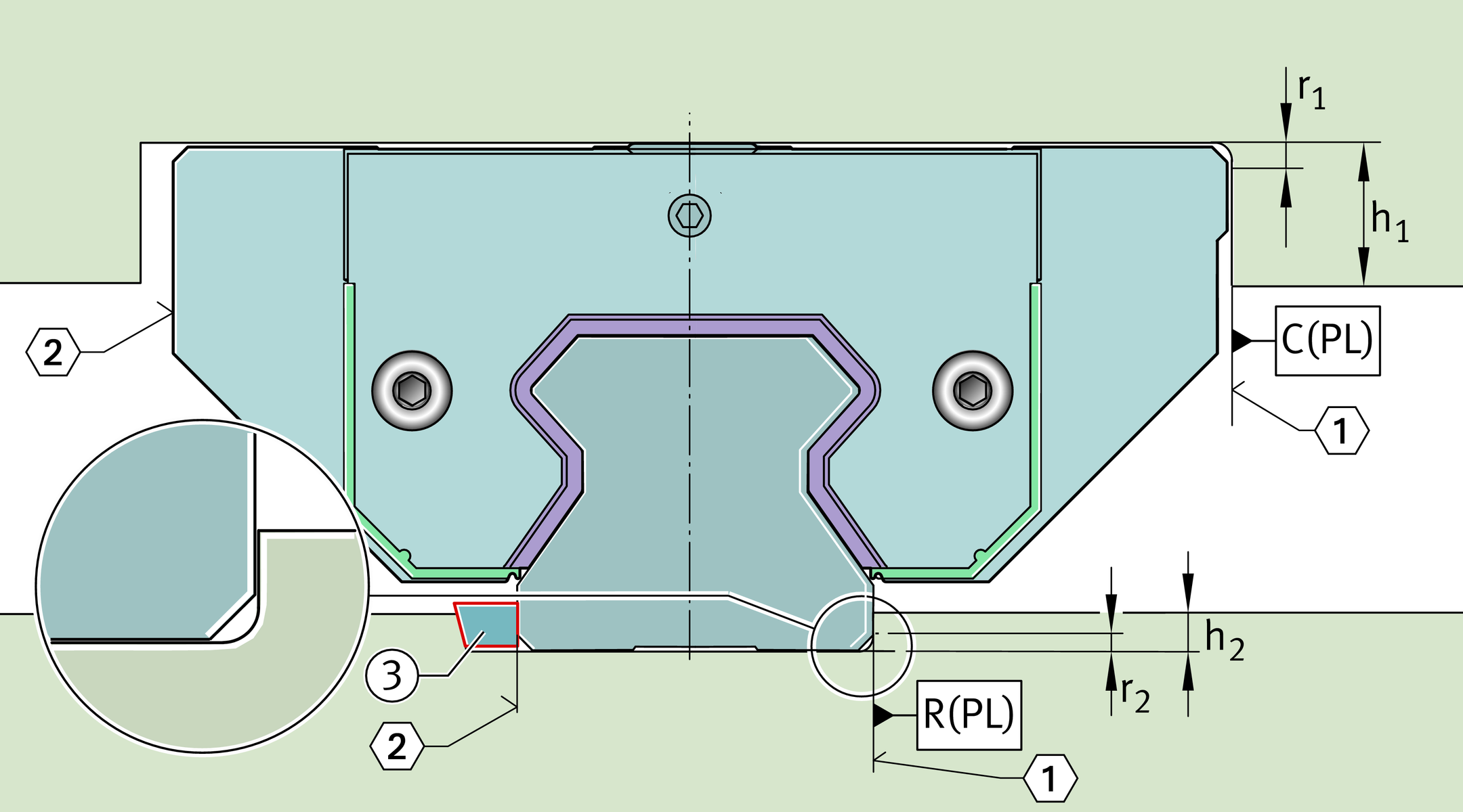
Locating heights and corner radii
For the design of locating heights and corner radii, see table and ➤ Figure.
Locating heights, corner radii
Designation | Locating heights | Corner radii | ||
|---|---|---|---|---|
h1 | h2 | r1 | r2 | |
mm | mm | mm | mm | |
max. | max. | max. | ||
RUE25-E (-L, -H, -HL)** | 7,5 | 4,5 | 0,8 | 0,3 |
RUE35-E (-L, -H, -HL) | 8 | 6 | 1 | 0,8 |
RUE45-E (-L, -H, -HL) | 10 | 8 | 1 | 0,8 |
RUE55-E (-L, -H, -HL) | 12 | 9,5 | 1 | 0,8 |
RUE65-E (-L, -H, -HL, -SL) | 15 | 10,5 | 1 | 0,8 |
RUE100-E-L | 25 | 13 | 1 | 0,8 |
**The linear recirculating roller bearing and guideway assembly RUE25-E is used in conjunction with the guideway TSX25-D.
Locating heights and corner radii
Accuracy
Accuracy classes
Linear recirculating roller bearing and guideway assemblies are available in the accuracy classes G0 to G3, ➤ Figure. The standard is class G2.
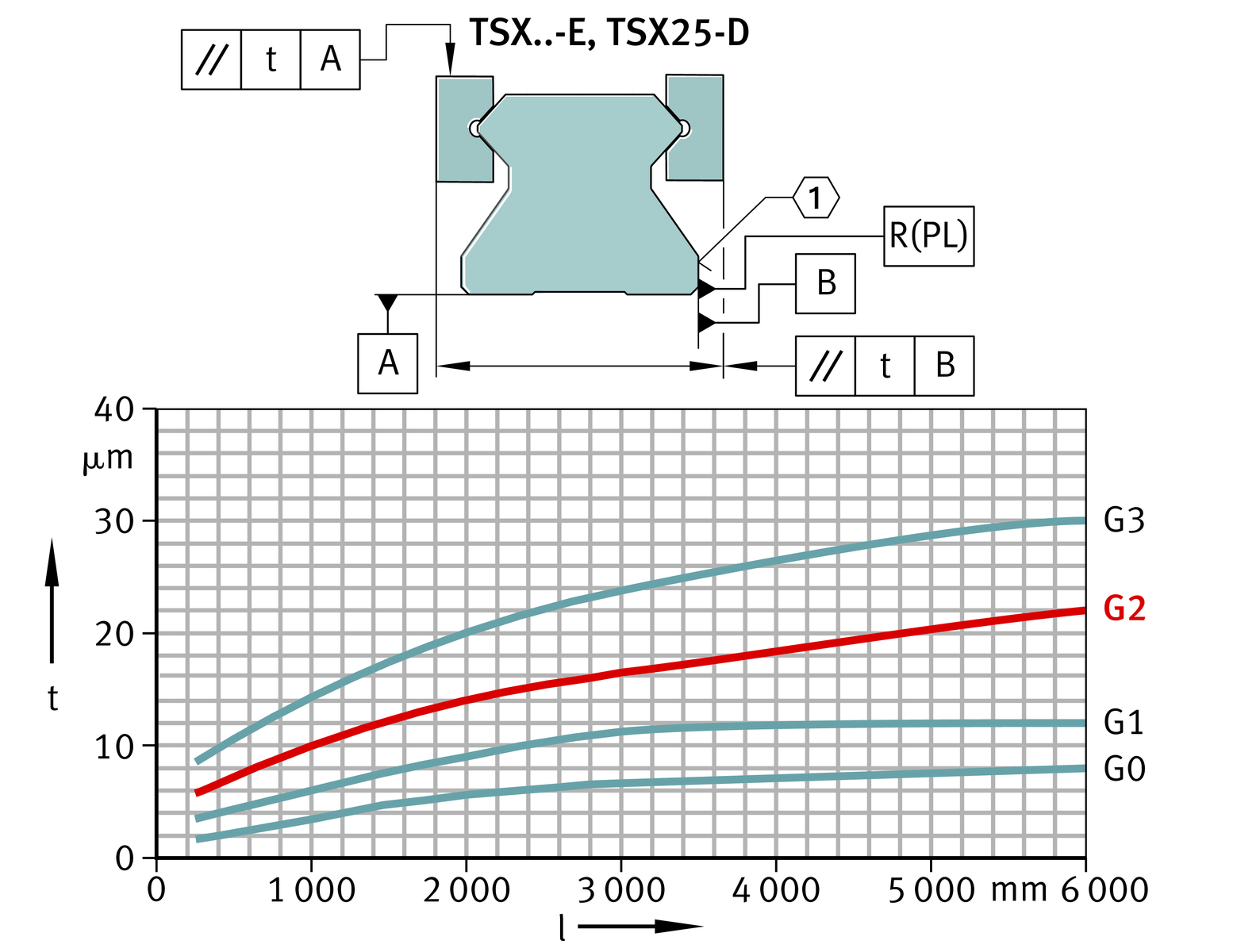
Parallelism of raceways to locating surfaces
The parallelism tolerance of the guideways is dependent on the accuracy class, ➤ Figure.
In coated systems, there may be deviations in tolerances compared with uncoated units.
Accuracy classes and parallelism tolerances of guideways
Running accuracy
The running accuracy is influenced by the accuracy of the adjacent construction.
Tolerances
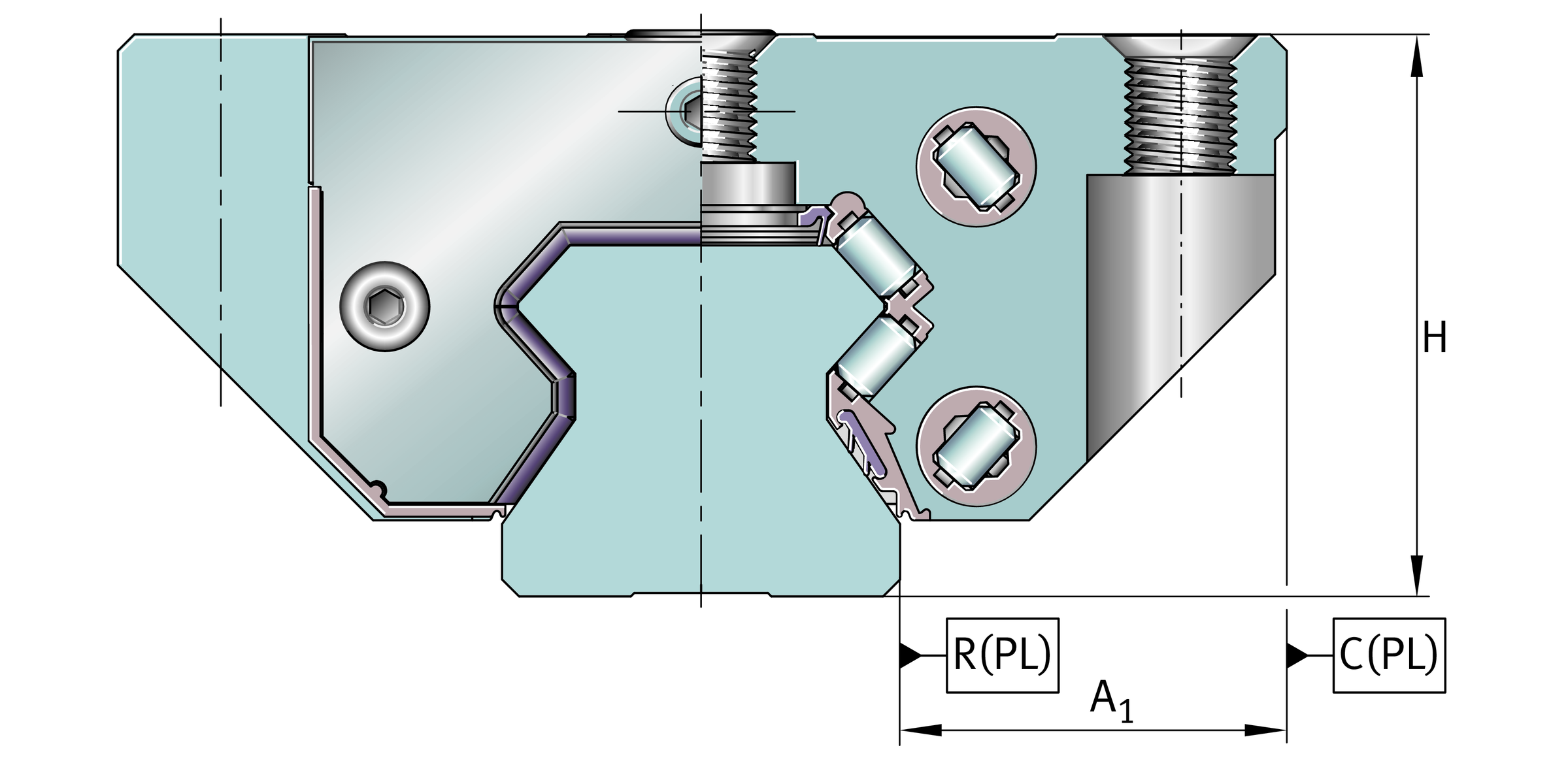
The tolerances are arithmetic mean values, see table and ➤ Figure. They are relative to the centre point of the screw mounting or locating faces of the carriage.
The dimensions H and A1 should always remain within the tolerance irrespective of the position of the carriage on the guideway, see table.
Tolerances for height H and spacing A1
Tolerance | Accuracy | ||||
|---|---|---|---|---|---|
G0 | G1 | G2** | G3 | ||
μm | μm | μm | μm | ||
Tolerance for height | H | ±5 | ±10 | ±20 | ±25 |
Difference in height** | ΔH | 3 | 5 | 10 | 15 |
Tolerance for spacing | A1 | ±5 | ±10 | ±15 | ±20 |
Difference in spacing** | ΔA1 | 3 | 7 | 15 | 22 |
**Standard accuracy class.
**Difference between several carriages on one guideway, measured at the same point on the guideway.
Datum dimensions for accuracy
Units with coating
For these units, the values for the appropriate accuracy class must be increased by the values for the coating, see table.
ACHTUNG
Coated systems are only available in the accuracy class G2.
Tolerances for coated parts
Tolerance** | Corrotect | Protect A | |
|---|---|---|---|
RROC | KD | ||
μm | μm | ||
Tolerance for height | H | +6 | +6 |
Difference in height** | ΔH | +3 | +3 |
Tolerance for spacing | A1 | +3 | +3 |
Difference in spacing** | ΔA1 | +3 | +3 |
**Displacement in tolerance zone (guideway and carriage with coating).
**Difference between several carriages on one guideway, measured at the same point on the guideway.
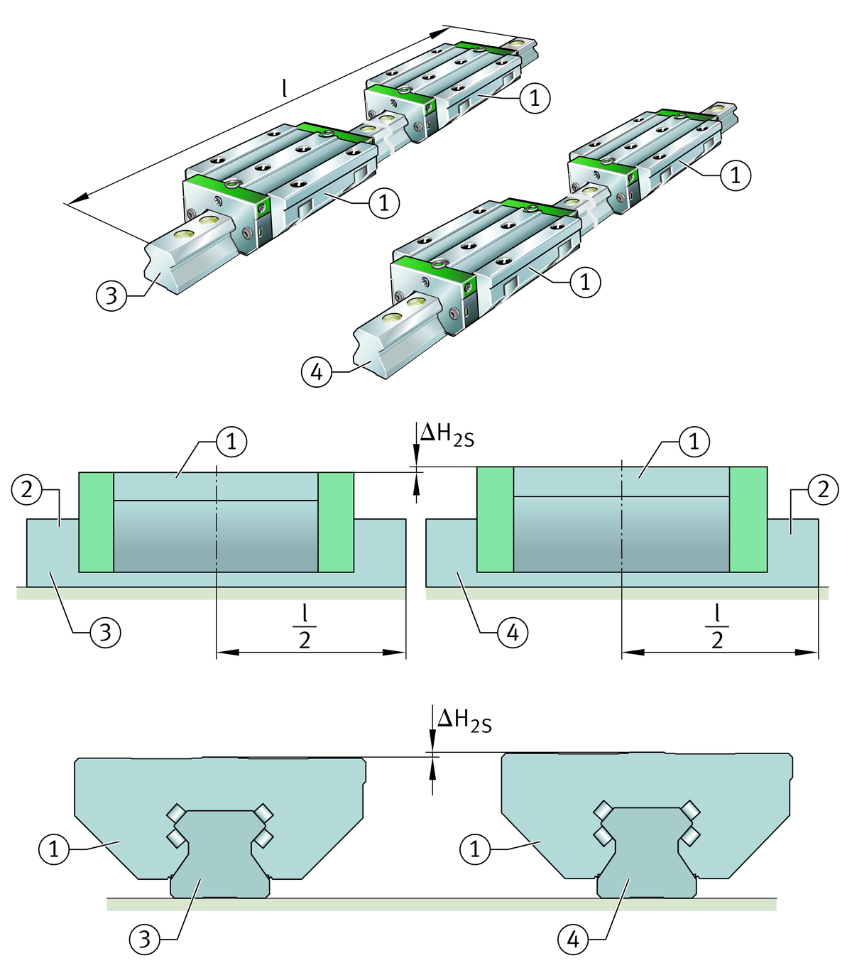
Height sorting 2S
If there are particular requirements for the accuracy of parallel systems, it is possible to restrict the height tolerance by specific sorting.
The height difference ΔH2S is measured at the centre of the guideway (l/2). At this point, the height difference between all carriages of linear recirculating roller bearing and guideway assemblies supplied as a set is max. ΔH2S, ➤ Figure and table.
Height sorting 2S

Height difference in 2S
Height difference | Accuracy | |||
|---|---|---|---|---|
G0 | G1 | G2 | G3 | |
μm | μm | μm | μm | |
ΔH2S** | 6 | 8 | 15 | 20 |
**Measured at the centre of the guideway.
Positional and length tolerances of guideways
The positional tolerances are not dependent on the guideway length, ➤ Figure and tables.
Positional and length tolerances of guideways
Length tolerances of guideways
Length tolerance | |||
|---|---|---|---|
Dependent on guideway length l | Multi-piece guideways | ||
mm | mm | ||
≦ 1 000 | 1 000 – 3 000 | > 3 000 | |
–1 | –1,5 | ±0,1% | ±3 |
ACHTUNG
If the ordering designation does not specify delivery of the guideway as a single piece, the guideway can optionally be supplied as several segments. Permissible pitch, see table.
Segments for multi-piece guideways
Guideway length** | Maximum permissible number of segments | |||
|---|---|---|---|---|
mm | ||||
< | 3 000 | 2 | ||
| 3 000 | – | 4 000 | 3 |
| 4 000 | – | 6 000 | 4 |
> | 6 000 | 4 plus 1 segment each of 1 500 mm | ||
**Minimum length of one segment = 600 mm.